Switchable phase locked loop and method for the operation of a switchable phase locked loop

a phase locked loop and switchable technology, applied in the field of phase locked loops, can solve the problems of disadvantageously small capture range of pll, difficult to achieve particularly low pll bandwidth in integrated circuit arrangement, and the compensation accuracy that can be achieved in practice, and achieve the effect of improving the phase locked loop

Inactive Publication Date: 2007-12-13
NAT SEMICON GERMANY
View PDF8 Cites 14 Cited by
  • Summary
  • Abstract
  • Description
  • Claims
  • Application Information

AI Technical Summary

Benefits of technology

[0011] An object of the present invention is to improve a phase locked loop or else a method of the type mentioned above, such that unwanted phase changes in the output signal resulting from a switchover can be reliably avoided.

Problems solved by technology

However, this solution includes for example the following two disadvantages: Firstly, a particularly low PLL bandwidth is hard to achieve in an integrated circuit arrangement.
Secondly, a low PLL bandwidth also results in a disadvantageously smaller capture range for the PLL.
A problem with this solution is the compensation accuracy that can be achieved in practice and the switching expenditure required for the compensation.

Method used


Image

  • Switchable phase locked loop and method for the operation of a switchable phase locked loop
  • Switchable phase locked loop and method for the operation of a switchable phase locked loop
  • Switchable phase locked loop and method for the operation of a switchable phase locked loop

Examples


Embodiment Construction

)

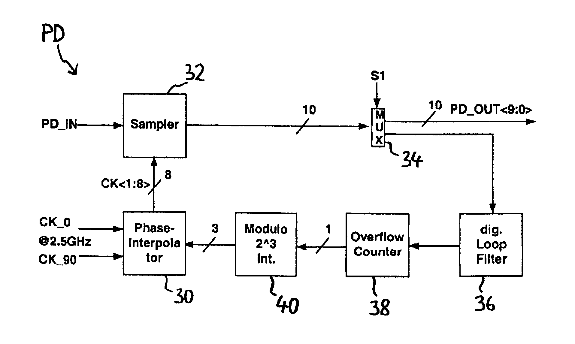
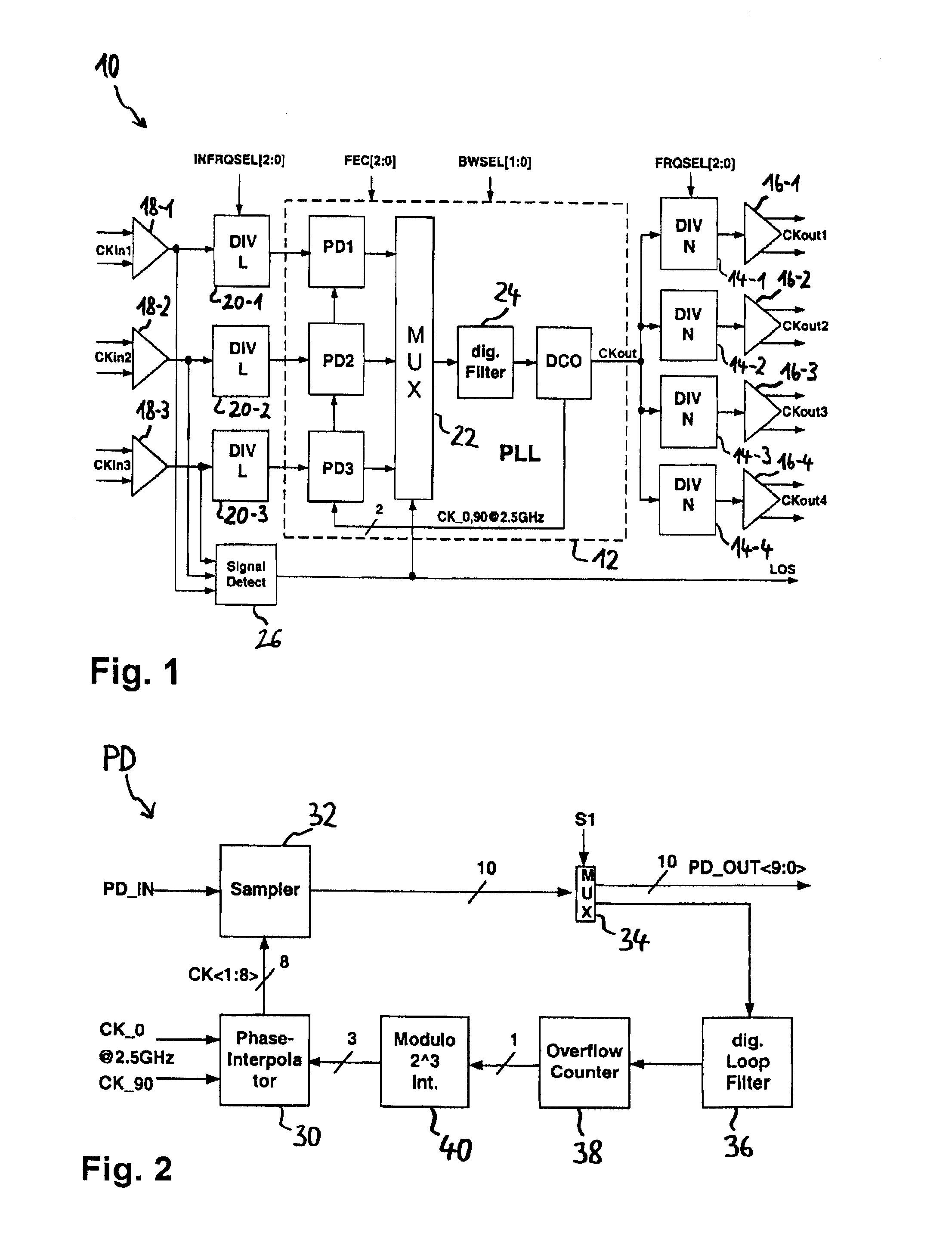
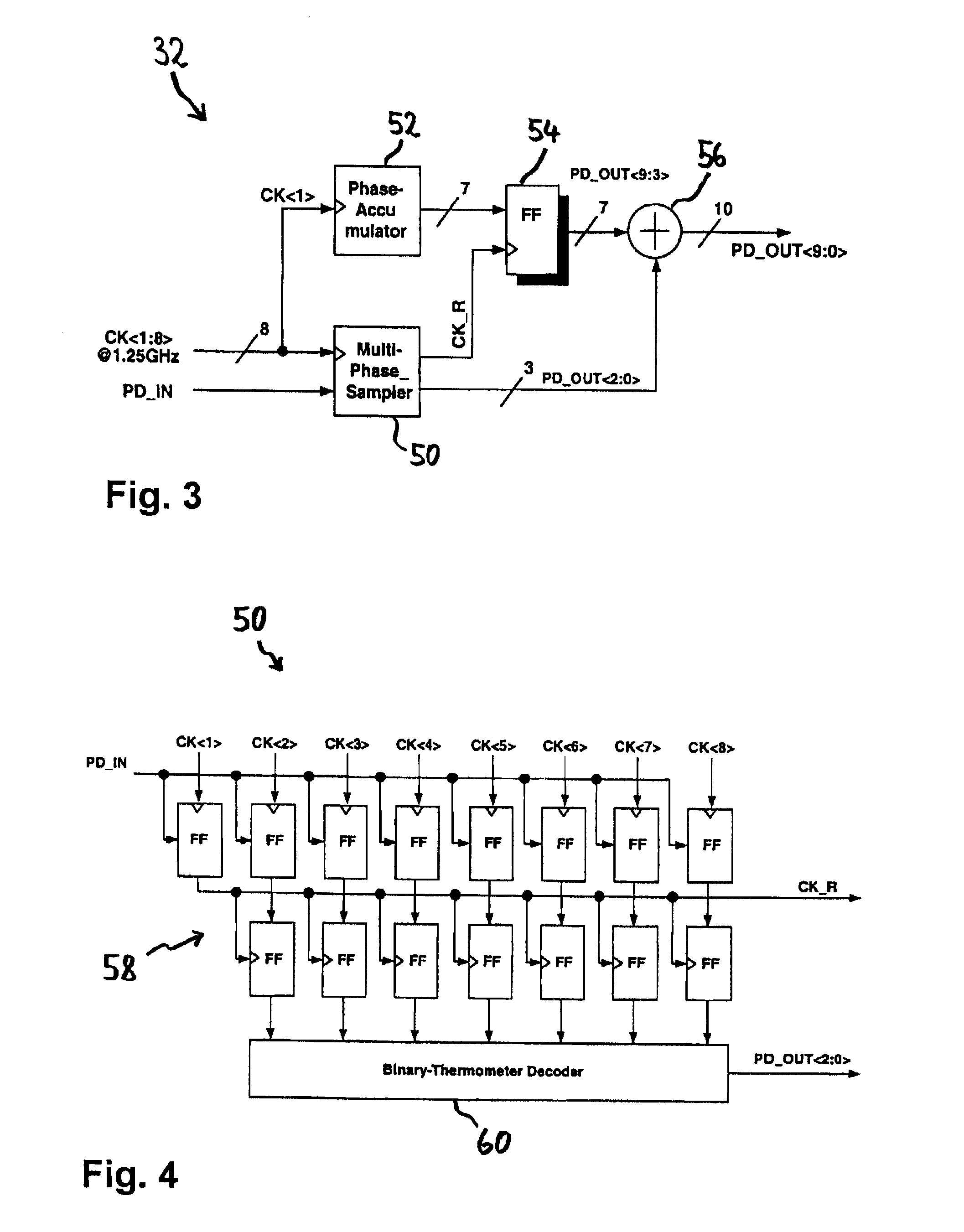
[0028]FIG. 1 shows a PLL circuit 10 with a PLL (phase locked loop) 12.

[0029] The PLL 12 has a digitally controlled oscillator (DCO) for generating an output signal CKout or else a two-phase version of this output signal with two phases CK_0 and CK_90. The two signals CK_0, CK_90 have a fixed phase difference relative to one another of 90° and fixed phase differences relative to the output signal CKout. In the simplest case, the signal CKout is identical to one of the signals CK_0 and CK_90.

[0030] In the exemplary embodiment shown, the PLL output signal CKout is fed to several output dividers 14-1 to 14-4, which divide the PLL output signal frequency in each case based on a predetermined division ratio and emit it to output stages 16-1 to 16-4, which convert the signal into a differential output clock CKout1 to CKout4 in each case.

[0031] At the input end, several differential clocks CKin1 to CKin3 are supplied to the circuit 10, which are initially converted into a non-differenti...


PUM


Abstract

The invention relates to a phase locked loop or “PLL” (12) and a method of operating a PLL (12), wherein a controllable oscillator (DCO) generates an output signal (CKout) and it is possible to switch between a first clock (CKin1 or CKin2) and a second clock (CKin2 or CKin1) for use as a PLL (12) input clock. In accordance with the invention, for the clock (CKin1 or CKin2) currently being used to generate the output signal (CKout) a phase difference is determined between this clock and a preset phase-shifted version (CK<1:8>) of the output signal (CKout) and is used to control the oscillator (DCO), whereas for the clock (CKin2 or CKin1) not currently being used to generate the output signal (CKout), the phase shift is adjusted. In this way, a phase difference between several clocks (CKin1, CKin2, CKin3) used as the input clock is effectively adjusted or else compensated before the switchover, so that any unwanted phase change in the PLL output signal resulting from the switchover can be avoided with a high degree of accuracy and hitless switching achieved.

Description

BACKGROUND OF THE INVENTION [0001] 1. Field of the Invention [0002] The present invention relates to a phase locked loop with a controllable oscillator for generating an output signal of the phase locked loop and with a switchover means for switching between a first clock and a second clock for use as the input clock of the phase locked loop. [0003] Further, the invention relates to a method of operating a phase locked loop, wherein a controllable oscillator generates an output signal of the phase locked loop and it is possible to switch between a first clock and a second clock for use as a phase locked loop input clock. [0004] 2. Description of the Prior Art [0005] A phase locked loop of this type, hereinafter also referred to in brief as “PLL”, and an operating method of this type for a PLL are known from U.S. Pat. No. 6,741,109, for example. [0006] In general terms, a PLL is used to synchronise a controlled oscillator, which generates an output signal with an output frequency, by...

Claims


Application Information

Patent Timeline
Patent Type & Authority Applications(United States)
IPC IPC(8): H03L7/00
CPCH03L7/0991H03L7/091H03L7/08
Inventor WERKER, HEINZ
Owner NAT SEMICON GERMANY
Why Eureka
Try Eureka