
Picture Information Encoding Apparatus and Picture Information Encoding Method

Inactive Publication Date: 2007-12-13
SONY CORP
View PDF1 Cites 47 Cited by
  • Summary
  • Abstract
  • Description
  • Claims
  • Application Information

AI Technical Summary

Benefits of technology

[0069] According to the present invention, even if a picture information encoding apparatus that outputs picture compression information according to a picture encoding system such as AVC cannot obtain vector information and so forth of adjacent blocks necessary for a parallel process such as a pipeline process, since the apparatus can generate pseudo information, a high speed encoding process can be accomplished.
[0070] In addition, according to the present invention, means for pseudo-computing moving vector information and reference index information that a picture information encoding apparatus that outputs picture compression information according to a picture encoding system such as AVC uses is provided to determine the skip mode or the spatial direct mode so as to accomplish a high speed parallel process and effectively set a mode.

Problems solved by technology

However, if each macro block that is pipeline-processed is not completed in a predetermined order, moving vector information of these adjacent macro blocks is not obtained.

Method used


Image

  • Picture Information Encoding Apparatus and Picture Information Encoding Method
  • Picture Information Encoding Apparatus and Picture Information Encoding Method
  • Picture Information Encoding Apparatus and Picture Information Encoding Method

Examples


first embodiment

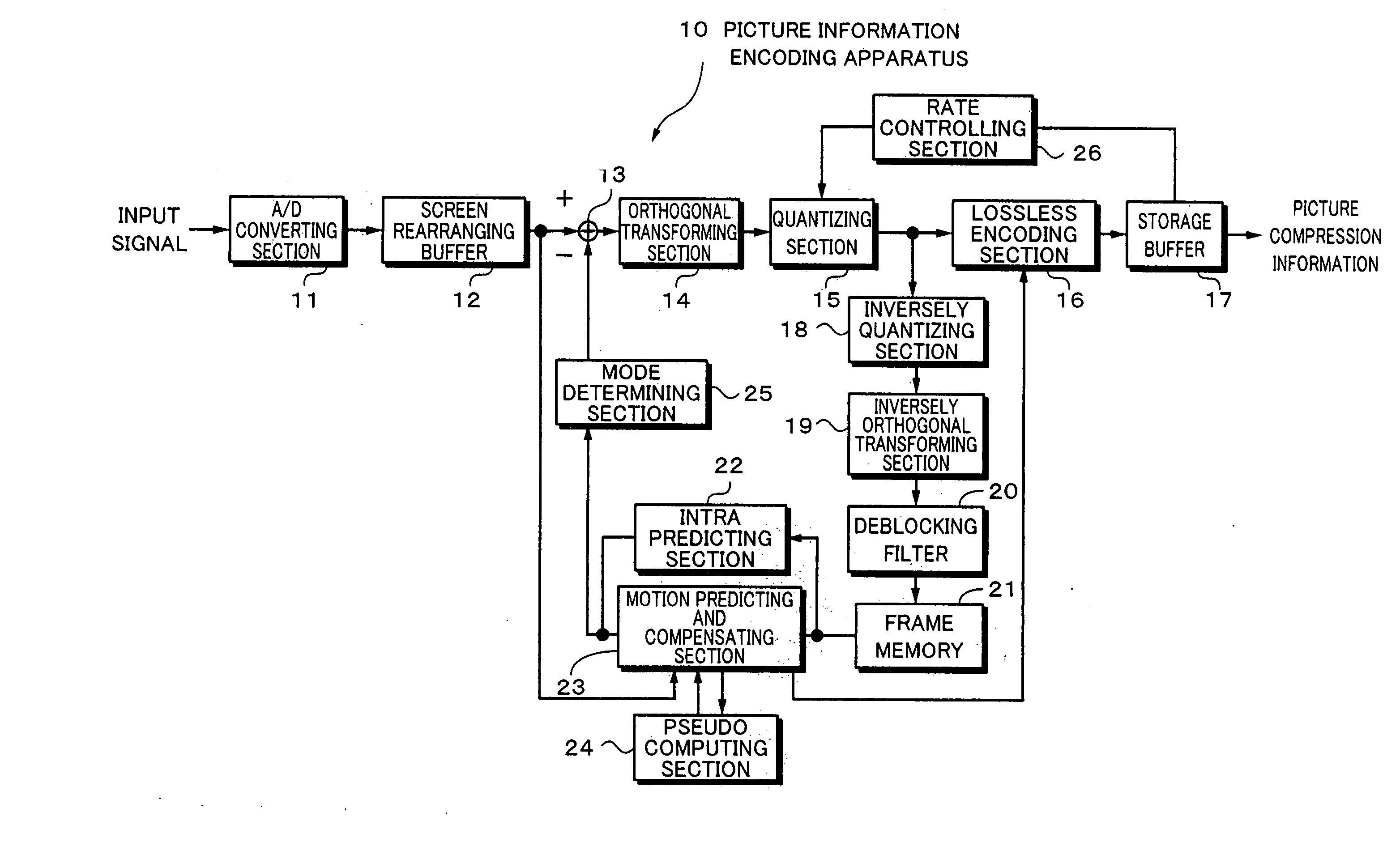
[0088] Next, with reference to FIG. 10, a picture information encoding apparatus according to the present invention will be described.

[0089]FIG. 10 is a block diagram showing a structure of the picture information encoding apparatus according to the first embodiment. The picture information encoding apparatus that is designated by reference numeral 10 has an A / D converting section 11, a screen rearranging buffer 12, an adding device 13, an orthogonal transforming section 14, a quantizing section 15, a lossless encoding section 16, a storage buffer 17, an inversely quantizing section 18, an inversely orthogonal transforming section 19, a deblocking filter 20, a frame memory 21, an intra-predicting section 22, a motion predicting and compensating section 23, a pseudo computing section 24, a mode determining section 25, and a rate controlling section 26.

[0090] The A / D converting section 11 converts an input analog picture signal into a digital picture signal and sends the digital pict...

second embodiment

[0118] the pseudo computing section 24′ may omit computing moving vector information with which it is determined whether the mode is the skip mode or the spatial direct mode.

[0119] Thus, the picture information encoding apparatus is structured so that it does not prevent a high speed parallel process from being preformed. This function can be implemented by a software system (software encoding) using a computer such as a PC (Personal Computer). For example, an embodiment using a PC including for example a CPU (Central Processing Unit), a memory, a hard disk, a record medium driving device, a network interface, and a bus that mutually connects these devices will be implemented.

[0120] In this embodiment, the CPU may be provided with a co-processor such as a DSP (Digital Signal Processor). The CPU executes functions of individual sections such as the foregoing A / D converting section 11 according to a command of a program loaded into the memory. When necessary, a memory that can be ac...


PUM


Abstract

In a picture information encoding apparatus that outputs picture compression information according to a picture encoding system such as MPEG4 / AVC, when it is determined whether the mode of a predetermined block is a skip mode or a spatial direct mode, moving vector information and so forth for all of predetermined adjacent blocks needs to have been computed. However, when each block is processed in parallel to speed up the entire processes, moving vector information and so forth of the predetermined adjacent blocks may not be always obtained. In this case, moving vector information and so forth of neighbor blocks instead of adjacent blocks are pseudo-used to determine the mode of the block without need to wait until moving vector information and so forth of adjacent blocks have been computed.

Description

TECHNICAL FIELD [0001] The present invention relates to a picture information encoding apparatus that is used when picture information (bit stream) that has been compressed by an orthogonal transforming process such as the discrete cosine transforming process or the Karnen-Loeve transforming process and a motion compensating process as in the MPEG (Moving Picture Experts Group) or H.26x is received through a network such as a satellite broadcast, a cable television, the Internet, or a cellular phone or when the picture information is processed on a record medium such as an optical disc, a magnetic disc, or a flash memory. BACKGROUND ART [0002] In recent years, a picture information encoding apparatus and a picture information decoding apparatus based on the MPEG, which deals picture information as digital information and compresses the picture information using redundancy, which comes with digital information, by an orthogonal transforming process such as the discrete cosine transfo...

Claims


Application Information

Patent Timeline
IPC IPC(8): H04N11/02H03M7/36H04N19/132H04N19/50H04N19/134H04N19/139H04N19/147H04N19/176H04N19/19H04N19/436H04N19/51H04N19/60H04N19/625H04N19/91
CPCH04N19/56H04N19/139H04N19/176H04N19/436H04N19/132H04N19/43H04N19/61H04N19/109
Inventor TSUCHIYA, TOSHIHARUSATO, KAZUSHIWADA, TORUYAGASAKI, YOICHIYAMADA, MAKOTO
Owner SONY CORP
Learn More