
Fuel cell having heat exchanger built in stack

a fuel cell and stack technology, applied in the field of fuel cells, can solve the problems of large space occupation, large overall volume of fuel cells, and insufficient electrical voltage generated by unit cells b>10/b> to be useful, so as to reduce space occupation and smoothly perform cooling and electricity generation functions.

Inactive Publication Date: 2007-12-13
SAMSUNG SDI CO LTD
View PDF7 Cites 21 Cited by
  • Summary
  • Abstract
  • Description
  • Claims
  • Application Information

AI Technical Summary

Benefits of technology

The present invention provides a fuel cell that has a reduced space occupancy and can smoothly perform cooling and electricity generation functions. The fuel cell includes a stack where a chemical reaction occurs and a heat exchanger that removes heat generated during the energy transformation process. The heat exchanger may be installed in one or more plates mounted in the stack, and may include a cooling water storage and a second cooling water flow channel to absorb heat from the cooling water storage. The cooling water storage may also include a first cooling water storage, a second cooling water storage that stores cooling water cooled by contacting the second cooling water flow channel, and a solenoid valve that selectively opens and closes a flow channel connecting the first and second cooling water storages. The technical effects of the invention include reduced space occupancy, improved cooling efficiency, and improved electricity generation performance.

Problems solved by technology

However, the electrical voltage generated from a unit cell 10 is generally not high enough to be useful.
Therefore, the overall volume of the fuel cell is large, and thus occupies a large space.
This is a drawback of the application of conventional fuel cells.
Also, flow channel lengths for the cooling water are increased according to an increase in the volume of the conventional fuel cell, thereby increasing heat loss.
This results in loss of the waste heat generated during the electricity production of the fuel cell for secondary purposes as well.

Method used


Image

  • Fuel cell having heat exchanger built in stack
  • Fuel cell having heat exchanger built in stack
  • Fuel cell having heat exchanger built in stack

Examples


Embodiment Construction

[0023]Reference will now be made in detail to the present embodiments of the present invention, examples of which are illustrated in the accompanying drawings, wherein like reference numerals refer to the like elements throughout. The embodiments are described below in order to explain the present invention by referring to the figures.

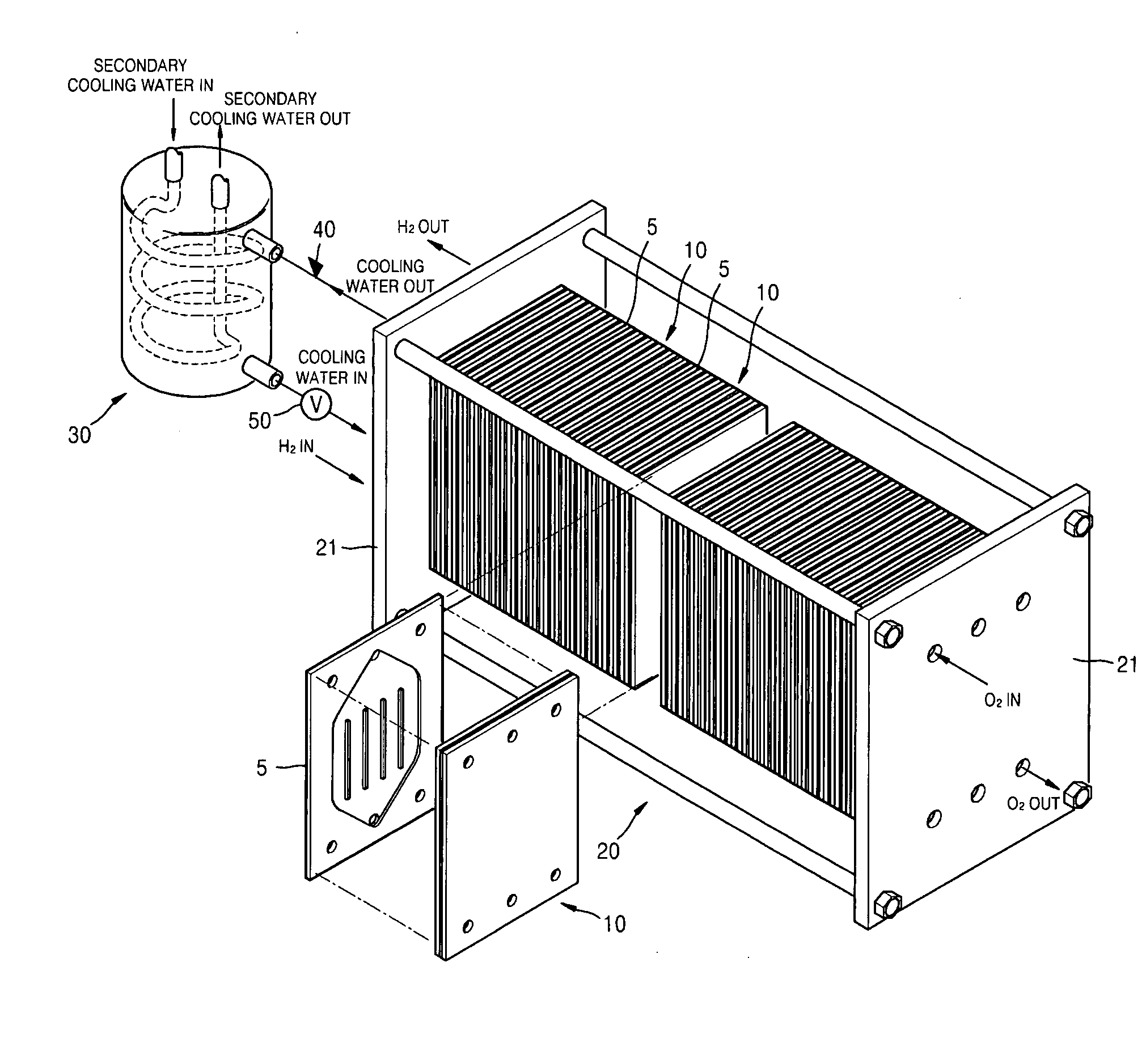
[0024]FIG. 4 is a perspective view of a fuel cell having a built-in heat exchanger according to an embodiment of the present invention. Referring to FIG. 4, a fuel cell according to an embodiment of the present invention includes a stack 100 in which a plurality of unit cells 10 where a chemical reaction that transforms chemical energy of a fuel into electrical energy are connected in series. Cooling plates 5 having a plurality of flow channels through which cooling water passes are installed in various positions in the stack 100. The cooling water that passes through the cooling plates 5 absorbs heat generated from the energy transformation process. O...


PUM

PropertyMeasurementUnit
chemical energyaaaaaaaaaa
temperatureaaaaaaaaaa
electrical energyaaaaaaaaaa

Abstract

A fuel cell having a heat exchanger that has a structure suitable for reducing space occupancy of the fuel cell. The fuel cell includes a stack where a chemical reaction for transforming chemical energy of a fuel into electricity occurs and a heat exchanger that removes heat generated during the energy transformation process in the stack, wherein the heat exchanger is built in at least one plate mounted on the stack. Therefore, the occupancy of the fuel cell can be reduced to be approximately half of a conventional externally mounted type heat exchanger.

Description

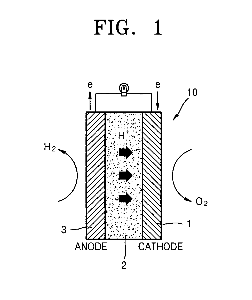
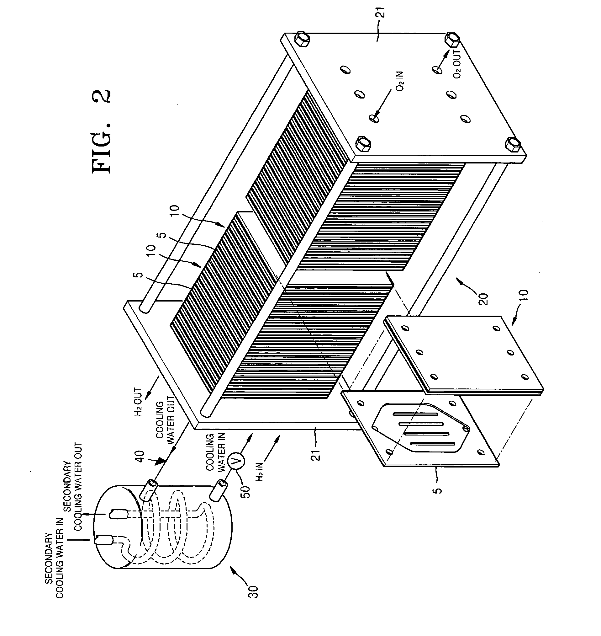
CROSS-REFERENCE TO RELATED PATENT APPLICATIONS[0001]This application claims the benefit of Korean Patent Application No. 2006-51986, filed Jun. 9, 2006, in the Korean Intellectual Property Office, the disclosure of which is incorporated herein in its entirety by reference.BACKGROUND OF THE INVENTION[0002]1. Field of the Invention[0003]Aspects of the present invention relate to a fuel cell, and more particularly, to a fuel cell including a stack with a built-in heat exchanger having a structure to advantageously reduce space occupancy of the fuel cell.[0004]2. Description of the Related Art[0005]In general, a fuel cell is an apparatus that directly transforms chemical energy of a fuel into electrical energy through a chemical reaction. A fuel cell can be described as a type of electric generator that can generate electricity as long as fuel is supplied.[0006]FIG. 1 is a schematic drawing showing the principle of generating electricity from a typical fuel cell, FIG. 2 is a perspective...

Claims


Application Information

Patent Timeline
Patent Type & Authority Applications(United States)
IPC IPC(8): H01M8/04
CPCH01M8/0267Y02E60/50H01M8/04074H01M8/04007H01M8/2483H01M8/04H01M8/02
Inventor LEE, SEUNG-JAESONG, TAE-WON
Owner SAMSUNG SDI CO LTD
Learn More