
Railway Track For Vehicles With Various Means Of Locomotion And Drive Systems, And Vehicle For Travelling On Said Railway Track

Inactive Publication Date: 2007-12-20
SOBOLEWSKI WALTER
View PDF6 Cites 31 Cited by
  • Summary
  • Abstract
  • Description
  • Claims
  • Application Information

AI Technical Summary

Benefits of technology

[0009] It is the object of the present invention to provide a railway track for vehicles having various means of locomotion and drive systems, on which smooth transitions among roadways are possible using the same vehicle. The multiple usage of a railway track is to increase transport performance and protect the environment and resources. Moreover, a vehicle is to be provided, which is adapted in the most optimal way to this railway track and, if necessary, also manages without this railway track.
[0018] Using the new achievement of the object, significantly less land is constructed on and investment costs are saved.
[0019] Through the use of magnetic levitation technology in all vehicle species and adaptation of the travel velocities to one another, a multiple performance increase is achieved when using the winged railway track.
[0020] The use of magnetic levitation technology on the trimodal roadway according to the present invention, which may be erected on the rail network and / or on the freeway, results in halving of the travel and freight times and is highly advantageous for the national economy.
[0022] The new winged railway track thus offers multiple advantages and applications. It may thus be used by a vehicle having a trimodal drive systems, which is advantageous, for example, if one of the drive systems, such as the levitation technology, breaks down or the vehicle wishes to leave this route in order to be able to come closer to urban centers, for example.

Problems solved by technology

The disadvantage of this system is that the vehicle is not optimally adapted to a magnetic levitation route and, in addition, this route may not be traveled by typical vehicles which are equipped with a drive system.
However, it is not known that motor vehicles having road wheels may travel on a railway track without additional aid.
However, it is not known that motor vehicles or magnetic levitation trains having two-part or four-part magnetic levitation technology may travel on a railway track.

Method used


Image

  • Railway Track For Vehicles With Various Means Of Locomotion And Drive Systems, And Vehicle For Travelling On Said Railway Track
  • Railway Track For Vehicles With Various Means Of Locomotion And Drive Systems, And Vehicle For Travelling On Said Railway Track
  • Railway Track For Vehicles With Various Means Of Locomotion And Drive Systems, And Vehicle For Travelling On Said Railway Track

Examples


Embodiment Construction

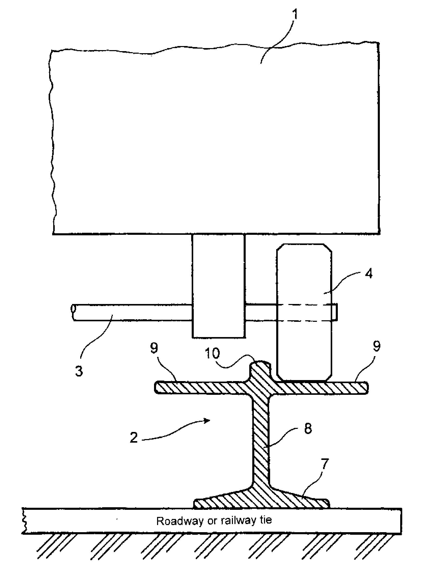
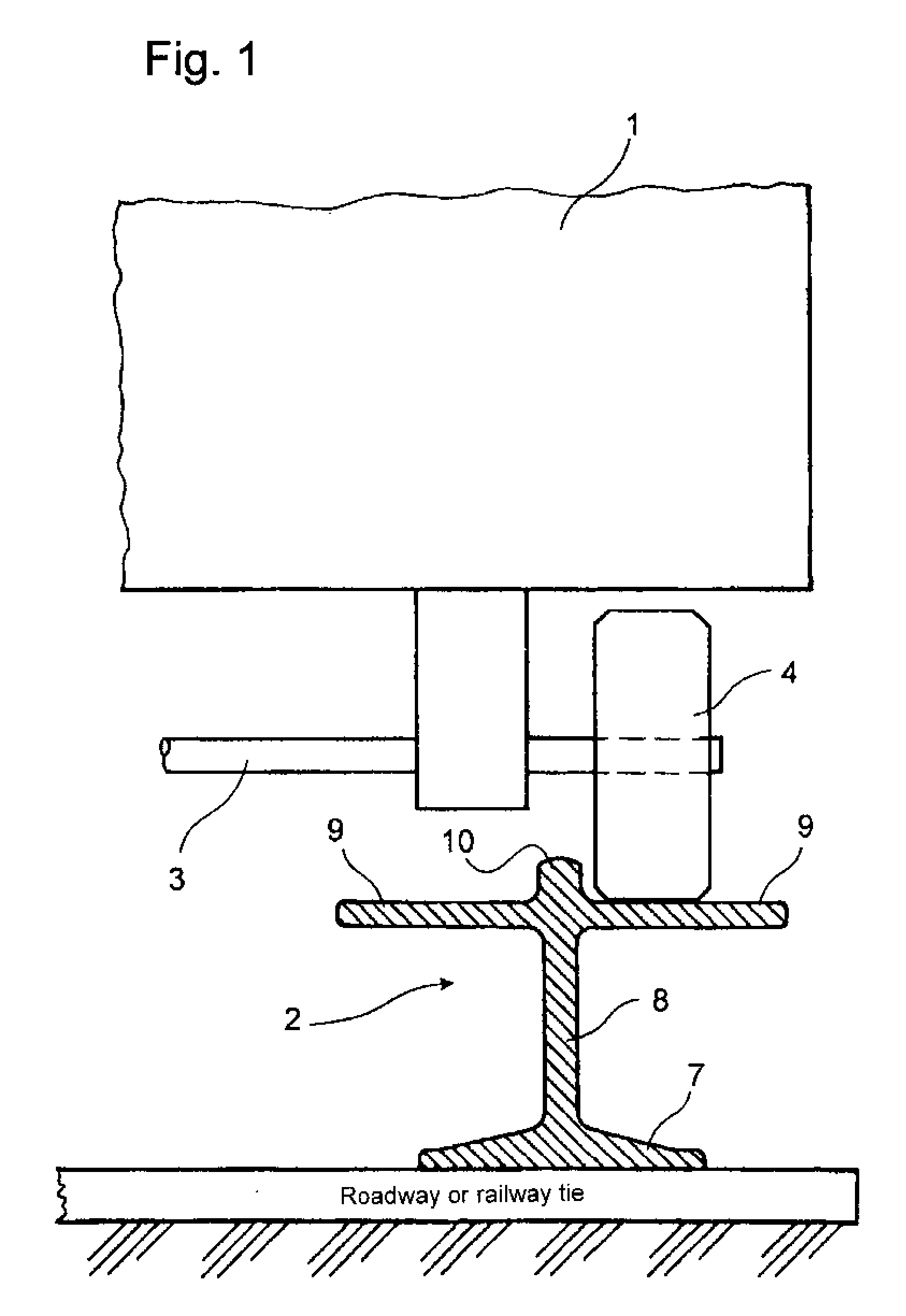
[0032]FIG. 1 shows a schematic illustration of a motor vehicle 1, which travels on a winged railway track 2 driven by a road wheel 4. The winged railway track 2 is equipped for alternative travel using three different travel systems.

[0033] To simplify the drawing, only one side of the vehicle 1 having a wheel 4 on an axle 3 is illustrated on a rail 7 of the winged railway track 2.

[0034] The rail 7 is implemented in the form of a stable double-T profile having a perpendicular traverse 8. The upper T-shape of the rail 7 has sufficient width so that the surface 9 thus formed, as shown in FIG. 1, may be traveled using the road wheel 4, but also using a rail vehicle (FIG. 4) or a magnetic levitation vehicle (FIG. 5).

[0035] A rail head 10 is arched in the middle of the surface 9 along the rail 7, which is supported by the traverse 8.

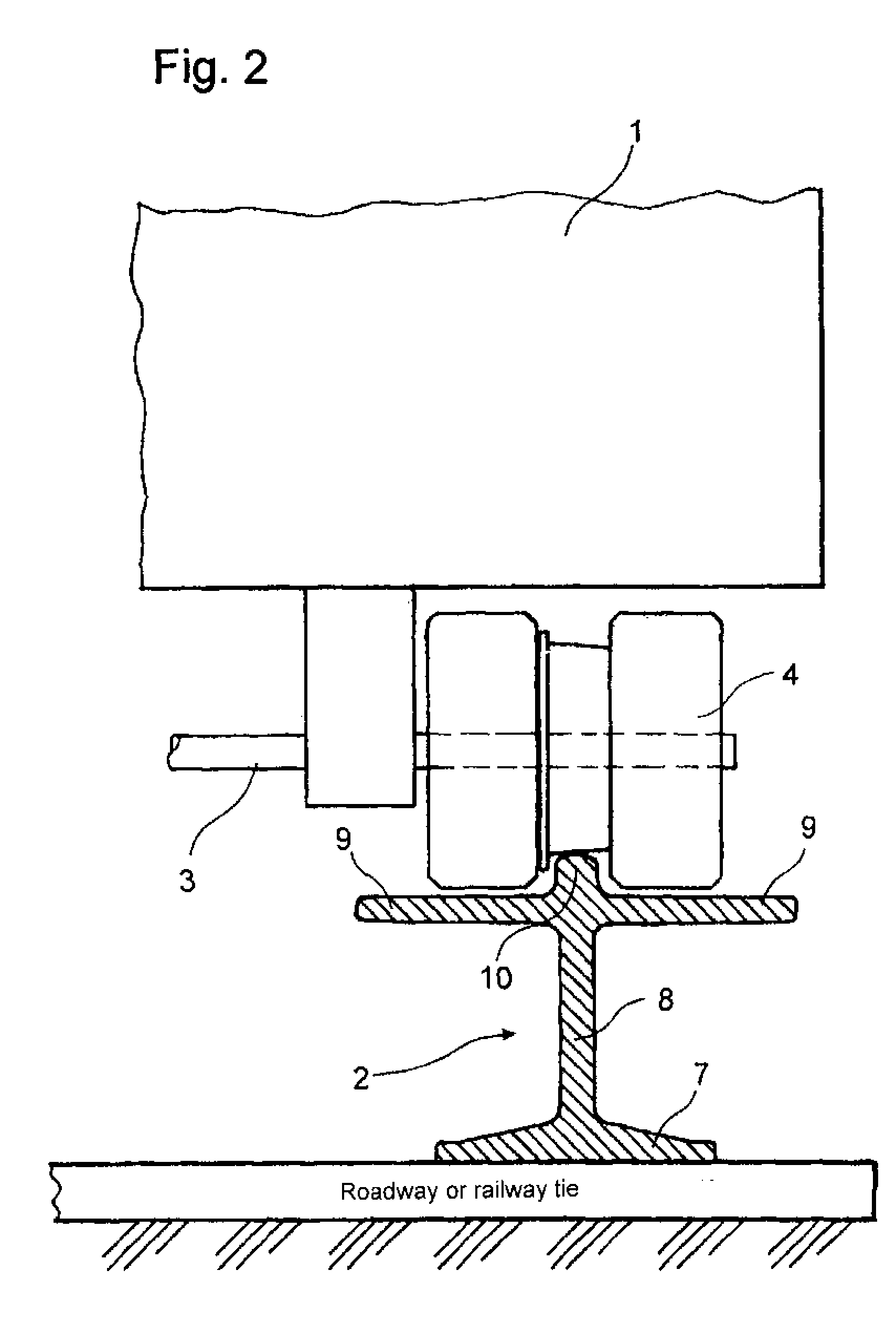
[0036]FIG. 2 shows a motor vehicle 1 which is driven using a flange wheel 5 and travels using its flange wheel 5 on the rail head 10.

[0037] The road whee...


PUM


Abstract

The invention relates to a railway track for vehicles with various means of locomotion and drive systems, enabling transitions from one type of roadway to another type of roadway to be carried out smoothly. The invention also relates to vehicle that is adapted to said railway track in an optimum manner and, if necessary, can travel without the railway track. The inventive railway track (2) consists of two parallel rails (7) provided with one or two wing-type extension arms (9), enabling vehicles to travel on the track with a flange wheel (5) as well as a road wheel (4), and with magnetic levitation (6). The vehicle (1) traveling on the railway track (2) can thus be embodied as a road, rail, or magnetic levitation vehicle and can also combine a plurality of means of locomotion and drive systems

Description

FIELD OF THE INVENTION [0001] The present invention relates to a railway track, which may be traveled by vehicles, such as motor vehicles, rail vehicles, and / or magnetic levitation vehicles having various means of locomotion and drive systems, such as a road wheels, flange wheels, and magnetic levitation technology. BACKGROUND OF THE INVENTION [0002] A multipurpose vehicle for using individual different and independent roadways is known from DE 101 25 617 A1 and DE 101 60 247 A1. [0003] This vehicle is alternatively designed for three types of locomotion such as wheel-road, wheel-rail, and magnetic levitation technology. It has a combined flange wheel and road wheel for the wheel-road and wheel-rail types of locomotion. For use as a magnetic levitation vehicle, at least four supports having current-carrying magnetic coils which may be extended and / or pivoted out are situated on both sides on the chassis and asynchronous short-stator motors are situated on the sides. [0004] For the t...

Claims


Application Information

Patent Timeline
IPC IPC(8): E01B25/28B60F1/02E01B25/30B61B13/00E01B5/02E01B7/00
CPCB60F1/005B60F1/02E01B25/305E01B7/00E01B5/02
Inventor SOBOLEWSKI, WALTER
Owner SOBOLEWSKI WALTER
Learn More