Vertical fluid power transmission and outboard engine system

a technology of vertical fluid and power transmission, which is applied in the direction of fluid couplings, gearings, vessel construction, etc., can solve the problems of easy deterioration and poor cooling, and achieve the effect of promoting cooling of working oil and downsizing the torque converter

Active Publication Date: 2007-12-20
HONDA MOTOR CO LTD
View PDF7 Cites 7 Cited by
  • Summary
  • Abstract
  • Description
  • Claims
  • Application Information

AI Technical Summary

Benefits of technology

[0007] The present invention has been achieved in view of the above circumstances, and has an object of the present invention is to provide a vertical fluid power transmission wherein an oil tank for storing a working oil of a torque conv

Problems solved by technology

Further, because the torque converter is the sealed-type, the working oil in the circulat

Method used


Image

  • Vertical fluid power transmission and outboard engine system
  • Vertical fluid power transmission and outboard engine system
  • Vertical fluid power transmission and outboard engine system

Examples


first embodiment

[0068] Now, operation of the first embodiment will be described below.

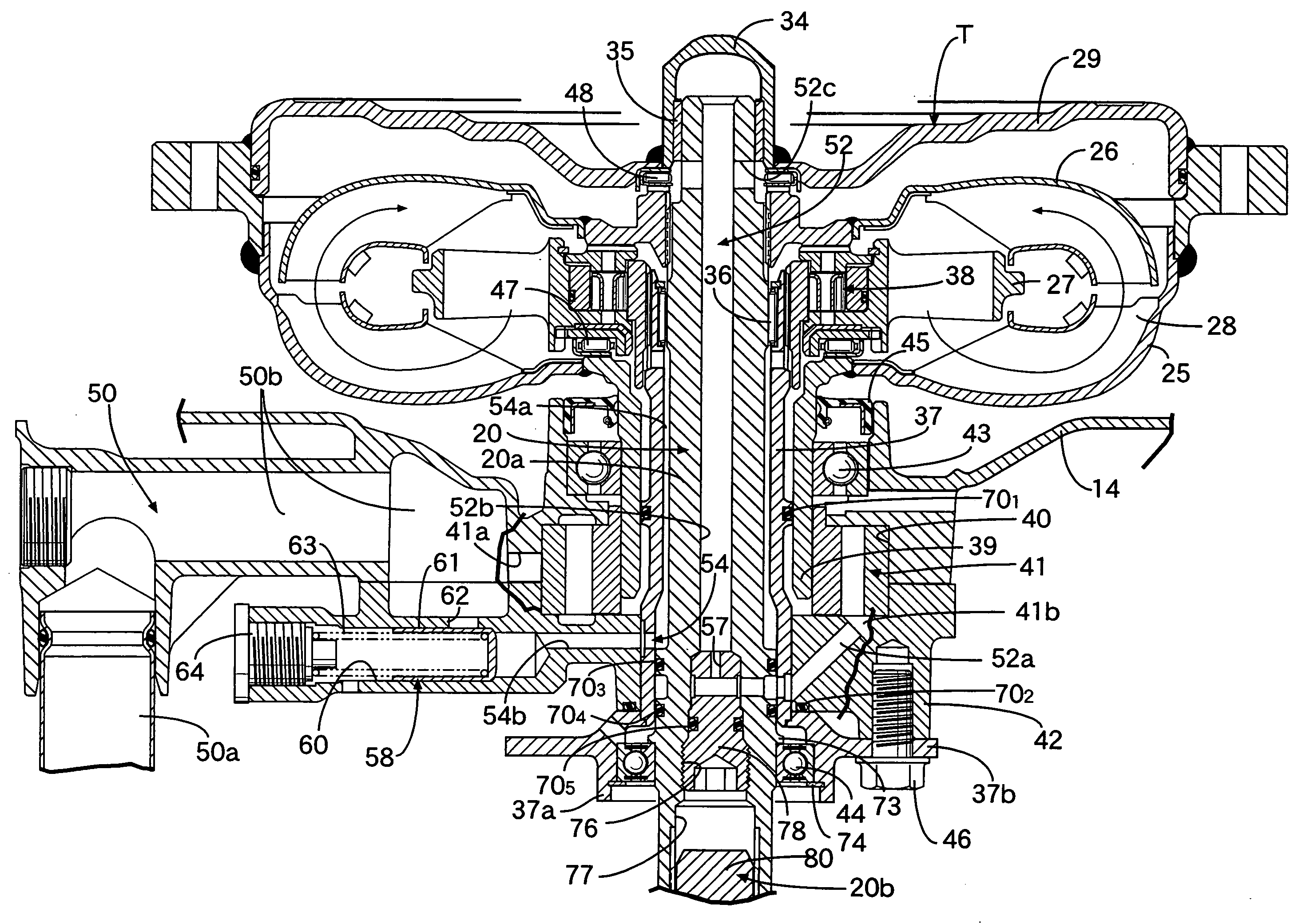
[0069] In operation of the engine E, the oil pump 41 is driven by the pump shaft 39 to draw up the oil 23 in the oil tank 22 through the oil suction passage 50, that is, through the suction tube 50a and the lateral oil passage 50b, and discharges the drawn-up oil 23 to the first oil supply passage 51 and the second oil supply passage 52. The oil discharged to the first oil supply passage 51 is supplied to the lubricated portion of the engine E, as described above.

[0070] Meanwhile, the oil supplied to the second oil supply passage 52 sequentially passes through the inlet oil passage 52a and the orifice 57; ascend through the vertical hole 52b of the upper output shaft 20a to go out of the horizontal hole 52c; enters the transmission cover 29 while lubricating the thrust needle bearing 48; and then flows into the circulation circuit 28 from the outer peripheral side of the turbine runner 26.

[0071] The oil in the c...

second embodiment

[0085] Next, the present invention shown in FIG. 6 to FIG. 9 will be described below. In FIG. 6, a first oil pump 24 is provided in a cylinder head of the engine E, and is driven by a cam shaft 82 for valve operation, the cam shaft 82 being supported by the cylinder head. The first oil pump 24 draws up the oil in the oil tank 22, and supplies the oil to a portion to be lubricated in the engine E. In FIGS. 7 and 8, an oil pump 41 driven at a lower end of a pump shaft 39 serves as the second oil pump 41 for drawing up the oil in the oil tank 22 to supply the oil to the circulation circuit 28 of the torque converter T. The passages of the oil discharged from the first and second oil pumps 24 and 41 will be described below by reference to FIG. 9.

[0086] The oil suction passage 50 extending from the single oil tank 22 is divided into first and second branched oil suction passages 50c an 50d, to which the first and second oil pumps 24 and 41 are connected, respectively. The first oil pump ...


PUM


Abstract

A vertical fluid power transmission includes: a vertical crankshaft of an engine; a vertical output shaft; and a vertical torque converter disposed between the crankshaft and the output shaft. An oil supply passage is connected to one end of the circulation circuit of the vertical torque converter, and guides a stored oil that is drawn up from an oil tank and discharged by an oil pump. An oil return passage is connected to the other one end of the circulation circuit, and leads to the oil tank. A normally-closed pressure response valve is provided in the oil return passage. The pressure response valve is opened by an upstream pressure. Thus, the oil tank for storing a working oil of the torque converter is separated from the torque converter, thereby downsizing the torque converter, and the working oil is circulated between the oil tank and the circulation circuit of the torque converter, thereby promoting cooling of the working oil.

Description

RELATED APPLICATION DATA [0001] The present invention is based upon Japanese priority application Nos. 2006-145961, 2006-145965 and 2006-145966, which are hereby incorporated in their entirety herein by reference. BACKGROUND OF THE INVENTION [0002] 1. Field of the Invention [0003] The present invention relates to an improvement of a vertical fluid power transmission comprising: a crankshaft of an engine, the crankshaft having an axis in a vertical direction; an output shaft having an axis in a vertical direction; and a torque converter which has an axis in a vertical direction, and is disposed between the crankshaft and the output shaft; the torque converter including a pump impeller connected to the crankshaft, a turbine runner connected to the output shaft so as to be opposed to the pump impeller, a stator arranged between the pump impeller and the turbine runner, and a circulation circuit of a power transmission oil, the circuit being defined between the pump impeller, turbine ru...

Claims


Application Information

Patent Timeline
IPC IPC(8): F16D33/02F01B1/02
CPCB63H20/002B63H20/14B63H20/20F16H57/04B63H23/30B63H2023/305F16H41/30B63H23/26
Inventor MATSUDA, YOSHIYUKIIDE, SHINICHI
Owner HONDA MOTOR CO LTD
Why Eureka
Try Eureka