
Maxium power point tracking method and tracking device thereof for a solar power system

a solar power system and tracking method technology, applied in the direction of electric variable regulation, process and machine control, instruments, etc., can solve the problems of increasing manufacturing costs and complicated structures, and achieve the effect of reducing manufacturing costs, maximum power point tracking methods, and simplifying the maximum power point tracking devices

Active Publication Date: 2007-12-20
ABLEREX ELECTRONICS CO LTD
View PDF9 Cites 28 Cited by
  • Summary
  • Abstract
  • Description
  • Claims
  • Application Information

AI Technical Summary

Benefits of technology

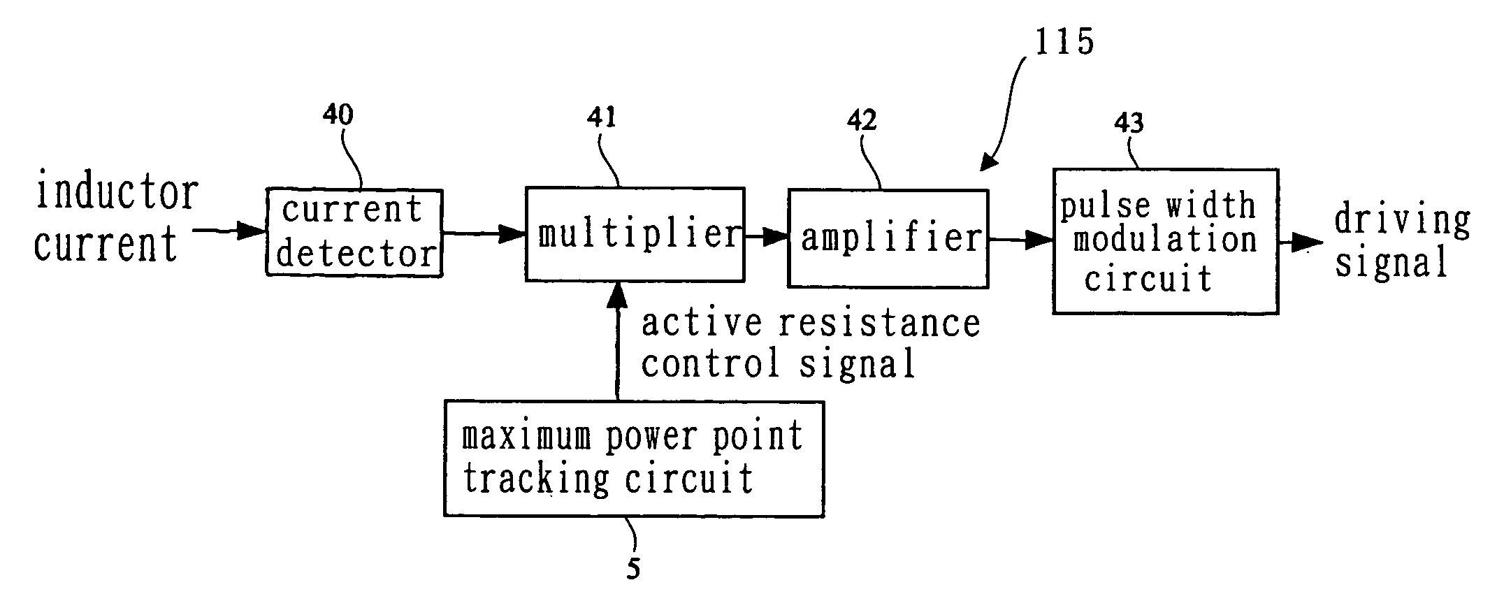
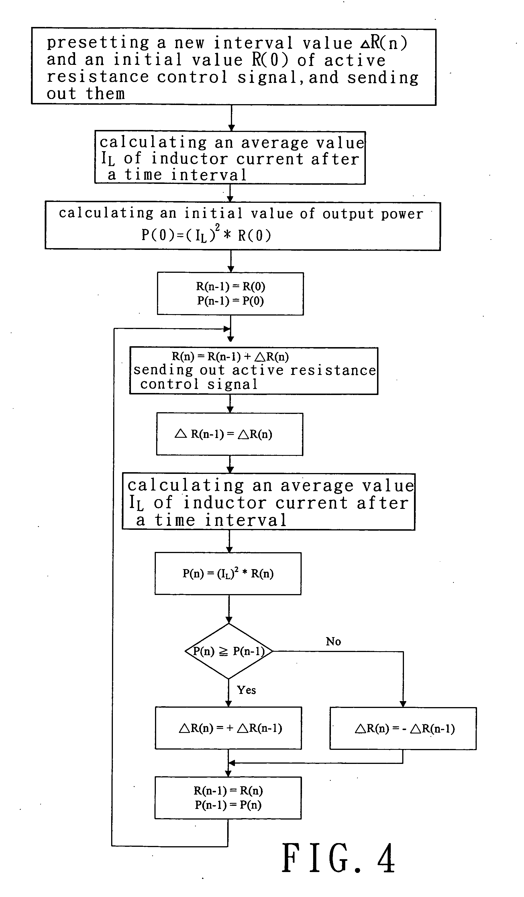
[0008]The primary objective of this invention is to provide a maximum power point tracking method and a maximum power point tracking device for a solar power system. A DC / DC converter connecting with a solar cell array is actuated to perform an active resistance characteristic for supplying power to a DC / AC inverter or a DC load. A maximum power point tracking circuit is further used to adjust the DC / DC converter for changing its active resistance, and to monitor a change of the solar cell array in output power. Accordingly, the maximum power point tracking method and the maximum power point tracking device are simplified, and manufacturing cost thereof is reduced.

Problems solved by technology

Secondly, an output power of the solar cell array is subsequently detected.
However, there exist some problems with practicing these perturbation methods applied to detect the maximum power point.
For example, the circuits of maximum power point tracking devices for use in practicing such perturbation and observation methods result in complication of structures, and increase the manufacturing costs.

Method used


Image

  • Maxium power point tracking method and tracking device thereof for a solar power system
  • Maxium power point tracking method and tracking device thereof for a solar power system
  • Maxium power point tracking method and tracking device thereof for a solar power system

Examples


Embodiment Construction

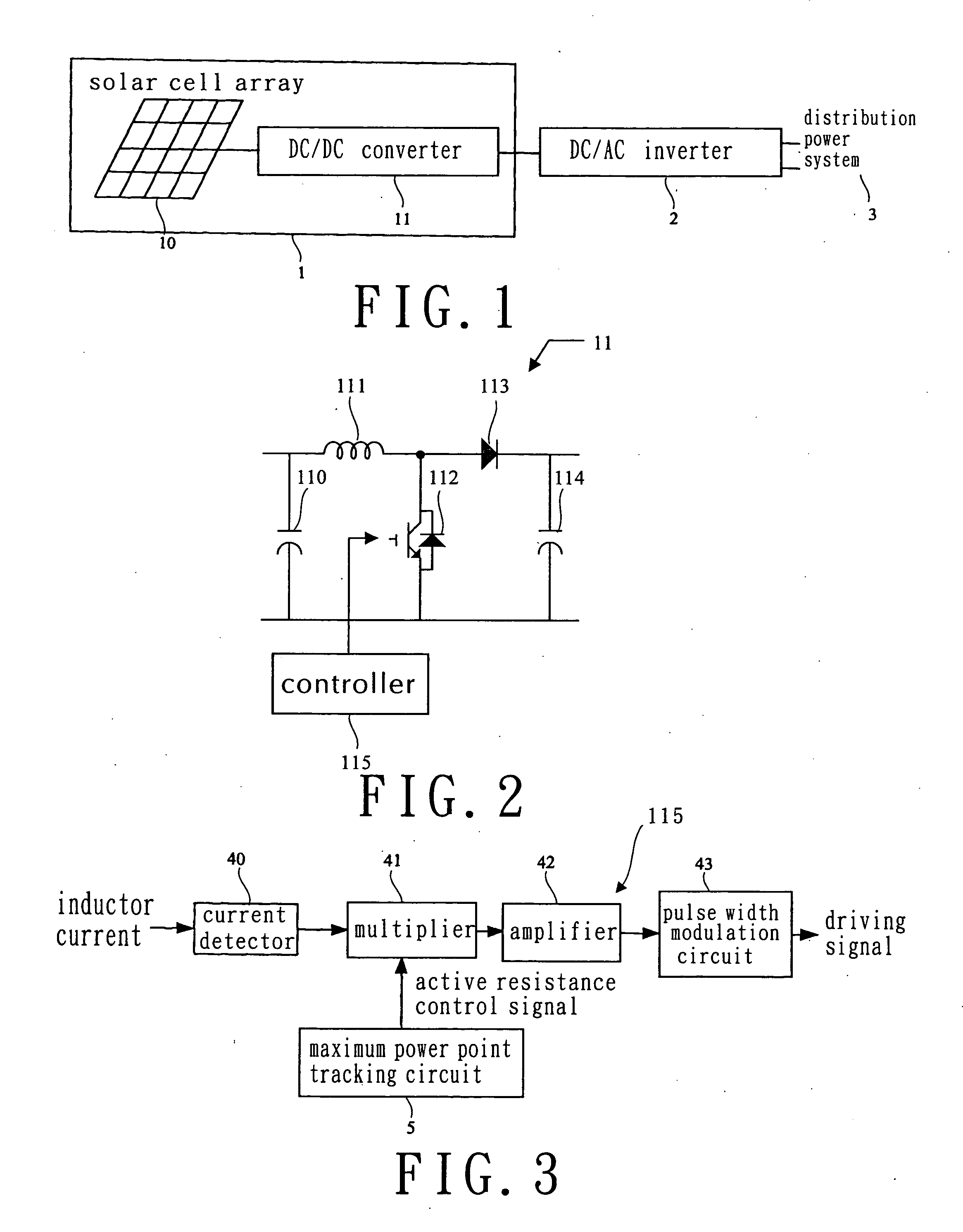
[0021]Turning now to FIG. 1, a schematic view of a solar power system in accordance with a first embodiment of the present invention is illustrated. Referring to FIG. 1, a solar power system 1 includes a solar cell array 10 and a DC / DC converter 11. The solar power system 1 connects with a DC / AC inverter 2 such that a DC power generated from the solar power system 1 can be sent to the DC / AC inverter 2 and converted into AC power to supply to a distribution power system 3. An output DC voltage of the DC / DC converter 11 controlled by the DC / AC inverter 2 can be constant or varied in response to the changes of the AC voltage of the distribution power system 3.

[0022]Turning now to FIG. 2, a schematic circuitry of the DC / DC converter applied in the maximum power point tracking device for the solar power system in accordance with a first embodiment of the present invention is illustrated. By referring to FIG. 2, the DC / DC converter 11 includes an input capacitor 110, an inductor 111, a po...


PUM


Abstract

A maximum power point tracking method, applied to a tracking device, employs a DC / DC converter connecting with a solar cell array, and including a controller actuating the DC / DC converter to perform an active resistance characteristic; a maximum power point tracking circuit adjusting the active resistance of the DC / DC converter; monitoring a change of an output power of the solar cell array in determining a direction for adjusting the active resistance of the DC / DC converter; and the maximum power point tracking circuit repeatedly adjusting the active resistance of the DC / DC converter. If the change of the output power of the solar cell array is positive, the active resistance of the DC / DC converter is adjusted in the same direction; but, conversely, if the change of the output power of the solar cell array is negative, the active resistance of the DC / DC converter is adjusted in an opposite direction.

Description

BACKGROUND OF THE INVENTION[0001]1. Field of the Invention[0002]The present invention relates to a maximum power point tracking method and a maximum power point tracking device for a solar power system. Particularly, the present invention relates to the maximum power point tracking method actuating a DC / DC converter to perform an active resistance characteristic so as to supply power to a DC / AC inverter or a DC load. More particularly, the present invention relates to the maximum power point tracking method that adjusts the DC / DC converter for changing its active resistance, and monitors a change of output power of a solar cell array.[0003]2. Description of the Related Art[0004]In solar power applications, a most significant subject focused today is associated with a technology of maximum power point tracking in addition to other major technologies which have been developed. Presently, a most common technology for maximum power point tracking is a perturbation and observation method...

Claims


Application Information

Patent Timeline
IPC IPC(8): G05F5/00
CPCG05F1/67Y02B70/12H02M3/157H02M1/42Y10S323/906Y02B70/10
Inventor CHOU, HUNG-LIANGCHIANG, WEN-JUNGWU, CHIN-CHANGFENG, YA-TSUNGLAI, LI-HSIANG
Owner ABLEREX ELECTRONICS CO LTD
Learn More