Display driver and display driving method

a technology of display driver and display device, applied in the field of display driver, can solve the problems of large amount of power and load on mpu, increased power consumption, and feared cost increase, and achieve the effect of preventing display with image distortion

Active Publication Date: 2007-12-20
RENESAS ELECTRONICS CORP
View PDF4 Cites 10 Cited by
  • Summary
  • Abstract
  • Description
  • Claims
  • Application Information

AI Technical Summary

Benefits of technology

[0012] A register capable of controlling external commands is prepared to control a switch so as to select a background pattern during changing a partial-display area. When an update ends, the switch is controlled so as to control image data of a partial memory. By this means, the display is the background pattern over the whole screen until the image data is switched according to setting a change of the partial-display area, thereby preventing display with image distortion.

Problems solved by technology

However, in recent years, while the progress of higher resolution due to demands of improvement in viewability and image quality, the power consumption increases.
Therefore, even for still images, it is required to execute image data transfer from the system of the previous stage such as a microprocessor (MPU: Micro Processing Unit) as needed, and so it causes a large amount of power and load on MPU.
However, as the progress in higher resolution in recent years as mentioned above, if the memory having a capacity for one screen image is equipped in the liquid crystal driver, it is feared to have a large increase in cost.

Method used


Image

  • Display driver and display driving method
  • Display driver and display driving method
  • Display driver and display driving method

Examples


first embodiment

[0027] A display driver and a driving method of an active-matrix display device according to a first embodiment of the present invention will be described with reference to FIG. 1 to FIG. 3. In this case, although a liquid crystal display device is described as one example of the active-matrix display device, it is applicable to other display devices such as organic EL display.

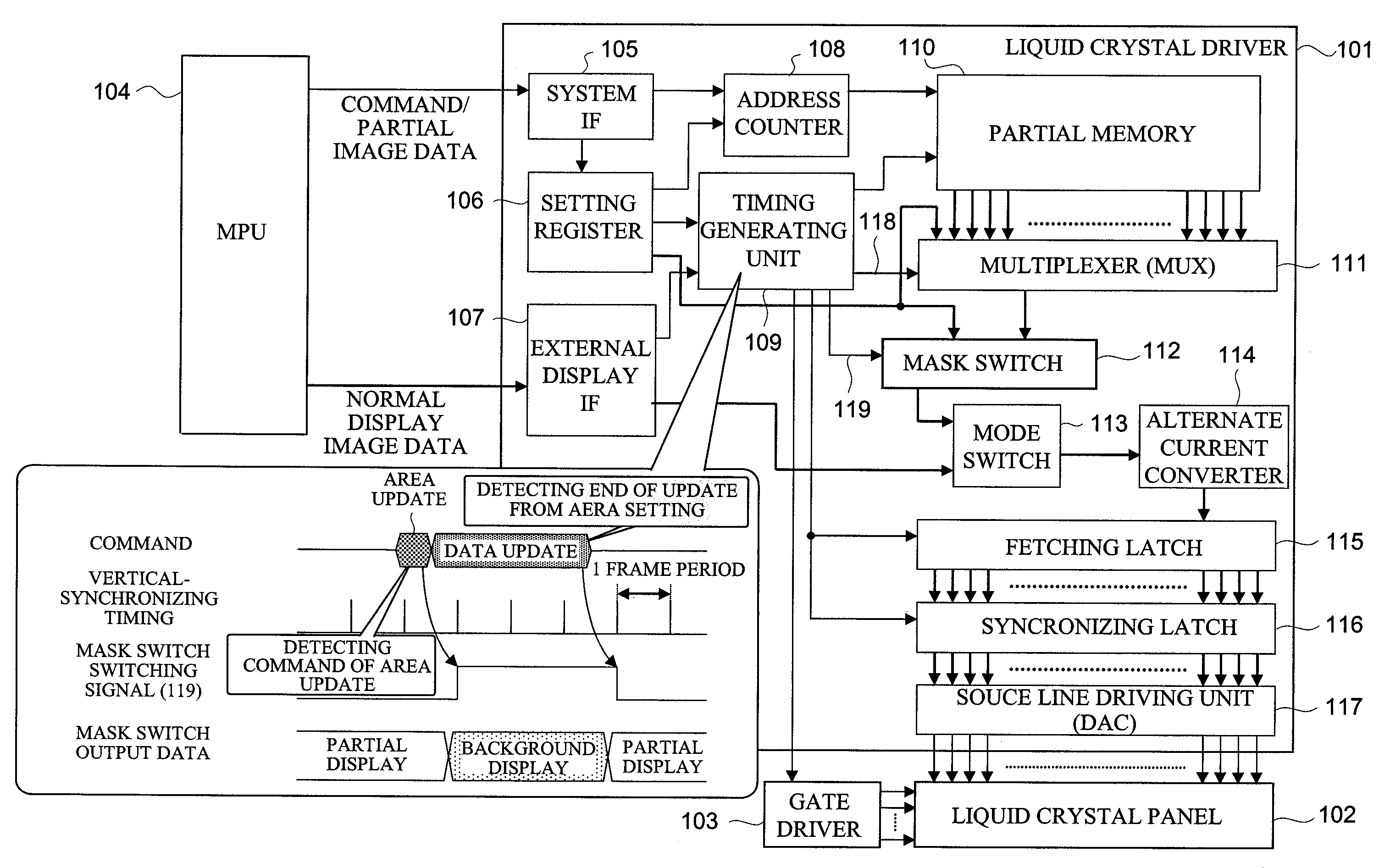
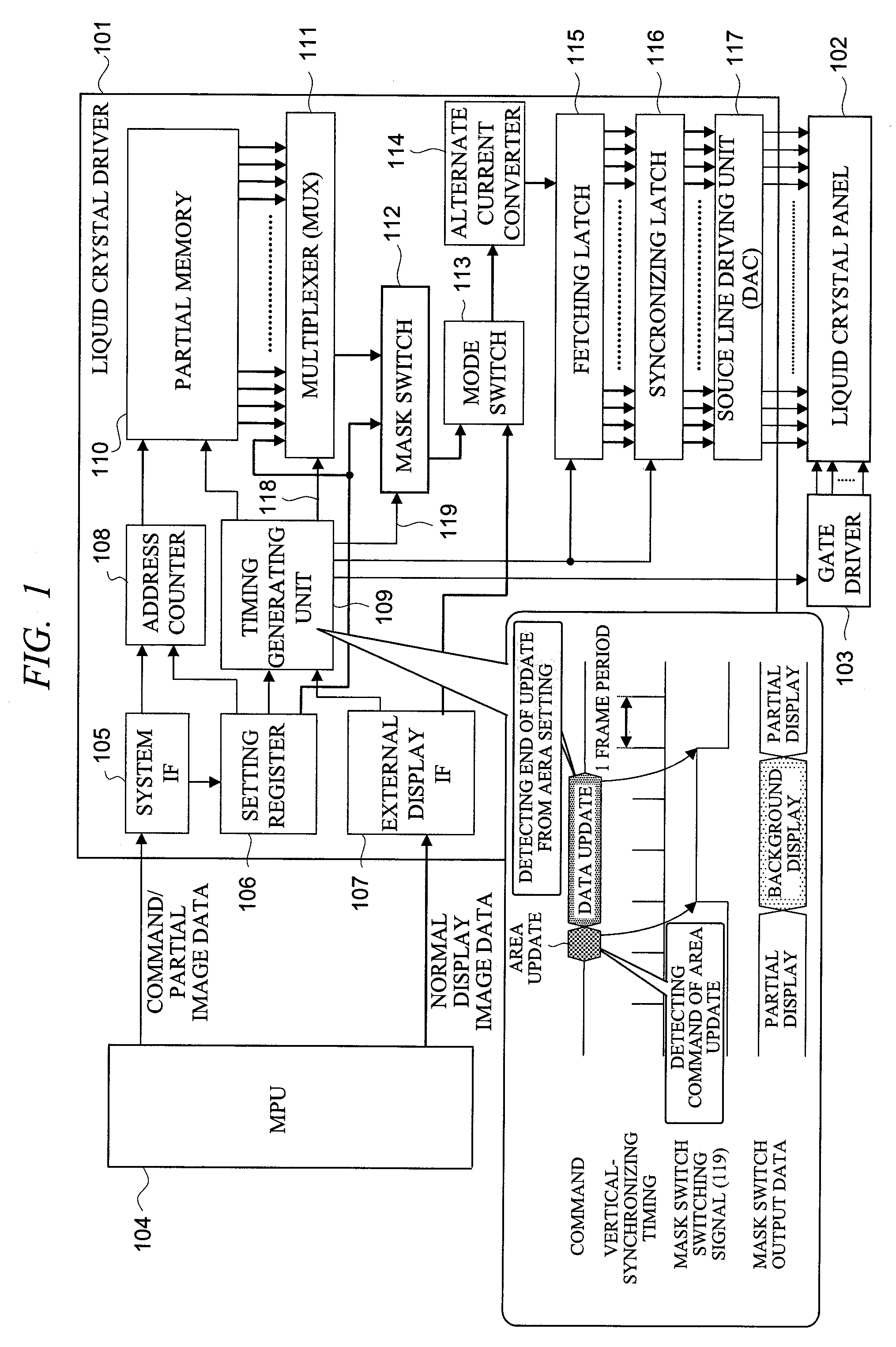
[0028]FIG. 1 shows a block diagram showing a liquid crystal driver of a liquid crystal display according to the first embodiment of the present invention and a connection relation with external devices thereof.

[0029] In FIG. 1, 101 indicates a liquid crystal driver as the display driver of the present invention, 102 indicates a liquid crystal panel of so-called active-matrix type, in which a liquid crystal pixels each is connected to a data line via a thin film transistor (TFT) and sandwiched between a pixel electrode and a common electrode are arranged on intersections of a plurality of scanning lines and a...

second embodiment

[0055] A display device according to a second embodiment of the present invention will be described with reference to FIG. 4.

[0056]FIG. 4 shows a liquid crystal driver of a liquid crystal display according to the second embodiment of the present invention and a connection relation with an external device thereof.

[0057] In the second embodiment, its block configuration is the same with FIG. 1 referred in the first embodiment and its operation is similar to that of the first embodiment. At the same time, a mask-switch-switching signal 119-a which controls the mask switch 112 as the switching means of the present invention is generated, and so it is a difference from the mask-switch-switching signal 119 in the first embodiment. Accordingly, the generation of the mask-switch-switching signal 119-a will be described.

[0058] The mask switch is controlled by the mask-switch-switching signal 119-a at the timing when receiving the mask validation command and the mask cancel command from th...

third embodiment

[0063] A display device according to a third embodiment will be described with reference to FIG. 5.

[0064]FIG. 5 shows a block configuration of a liquid crystal driver of a liquid crystal display according to the third embodiment of the present invention and a connection relation with external devices thereof.

[0065] In the third embodiment, the mask switch 112 in FIG. 1 (first embodiment) and FIG. 4 (second embodiment) is used for both functions of switching partial validation period and the background pattern. Meanwhile, other operations and effects are the same with those of the first embodiment and the second embodiment.

[0066] In the third embodiment, a control-signal-masking circuit 301 as a masking means is added, which masks the partial-display timing 118 by the mask-switch-switching signal 119 and generates partial-display timing 118-a which does not validate displaying when updating the partial-display data. The control signal masking circuit 301 generates the partial-disp...


PUM


Abstract

In a liquid crystal driver of a liquid crystal display having a structure to switch between image data for partial display from a partial memory and non-display (background pattern), changes in a partial-display area is detected according to a setting command of partial-display area, and a mask switch is controlled so as to select the background pattern. Timing to write to the last line of the changed partial-display area in the partial memory is determined by an address counter for controlling the partial memory, and the mask switch is controlled so as to select the image data of the partial memory from the next frame.

Description

CROSS-REFERENCE TO RELATED APPLICATION [0001] The present application claims priority from Japanese Patent Application No. JP 2006-137357 filed on May 17, 2006, the content of which is hereby incorporated by reference into this application. BACKGROUND OF THE INVENTION [0002] The present invention relates to a display driver which drives an image display device such as Liquid Crystal Display, more particularly, a technique effectively applied to a drive circuit and a driving method of an active-matrix display device having means of partial display. [0003] For example, active-matrix display devices are used for mobile devices such as mobile phones and handheld terminals, because of their features such as thin, light, and low power consumption. For mobile devices, generally the power supply is made by batteries and so improvement in lowering of power consumption is required. However, in recent years, while the progress of higher resolution due to demands of improvement in viewability a...

Claims


Application Information

Patent Timeline
Patent Type & Authority Applications(United States)
IPC IPC(8): G06F3/038
CPCG09G3/3648G09G2340/12G09G2310/04G09G5/397
Inventor AWAKURA, HIROKIKUDO, YASUYUKISHOJI, TAKASHIOTA, SHIGERU
Owner RENESAS ELECTRONICS CORP
Why Eureka
Try Eureka