Check patentability & draft patents in minutes with Patsnap Eureka AI!

X-ray CT data acquisition method and x-ray CT apparatus

Active Publication Date: 2007-12-20
GE MEDICAL SYST GLOBAL TECH CO LLC
View PDF21 Cites 6 Cited by
  • Summary
  • Abstract
  • Description
  • Claims
  • Application Information

AI Technical Summary

Benefits of technology

[0022] In the X-ray CT data acquisition method in accordance with the fifth aspect described above, the amount of table resting T, which is the value obtained by dividing the holding time τ by the one rotation time R, is set larger when the velocity V of the linear movement is faster. In this manner the projection data in the view angle range required for the image reconstruction may be positively acquired thereby, when the one rotation time R is slower, and the velocity V of the linear movement is faster.
[0027] The time spend for acquiring the projection data in the view angle range required for the image reconstruction becomes shorter when the width of the image extension area d becomes larger.
[0033] The time spent for acquiring the projection data in the view angle range required for the image reconstruction becomes shorter when the one rotation time R is slower and when the width of the image extension area d is larger.
[0054] In the X-ray CT data acquisition method and X-ray CT apparatus in accordance with the present invention, the projection data can be positively acquired for reconstructing an image at a slice position outside the linear movement range in the helical scan, helical shuttle, or variable helical pitch scan.

Problems solved by technology

There arose a problem that, if either the rotating velocity is too slow or the linear movement velocity is too fast, acquirable position may be passed over before acquiring the projection data of the view angle range required to reconstruct the CT image at the slice position outside the linear movement range.

Method used


Image

  • X-ray CT data acquisition method and x-ray CT apparatus
  • X-ray CT data acquisition method and x-ray CT apparatus
  • X-ray CT data acquisition method and x-ray CT apparatus

Examples


first embodiment

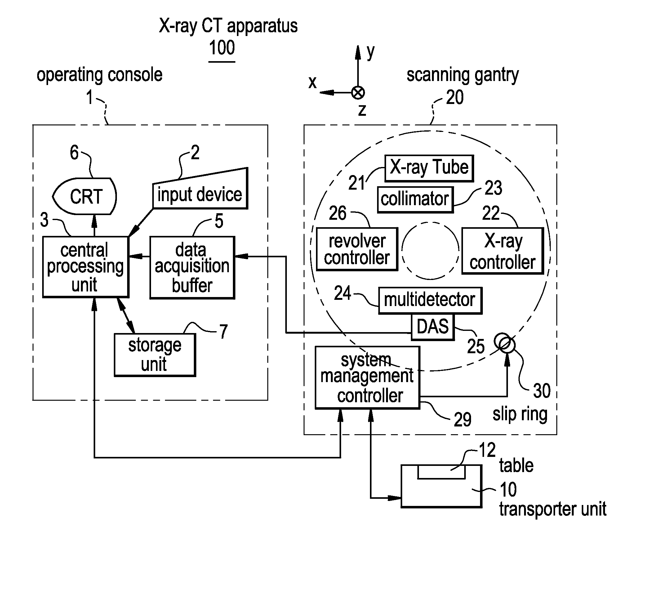
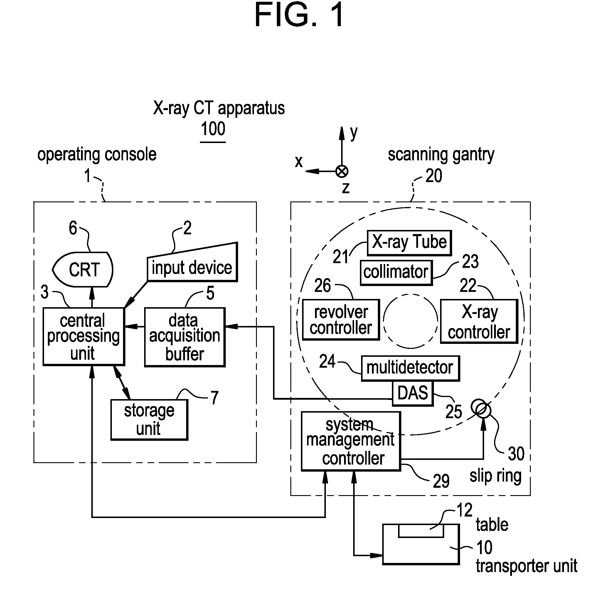
[0063] Now referring to FIG. 1, there is shown a schematic diagram illustrating an X-ray CT apparatus 100 in accordance with first preferred embodiment of the present invention.

[0064] The X-ray CT apparatus 100 includes an operating console 1, a transporter unit 10, and a scanning gantry 20.

[0065] The operating console 1 includes an input device 2 for receiving the input from an operator, a central processing unit 3 performing processing such as the image reconstruction, a data acquisition buffer 5 for acquiring projection data obtained from the scanning gantry 20, a CRT 6 for displaying a CT image reconstructed from the projection data, and a storage unit 7 for storing the programs, data, and X-ray CT images.

[0066] The transporter unit 10 includes a table 12 to carrying thereon an object to be imaged and carrying in to and out from the bore (central core) of the scanning gantry 20. The table 12 is elevated up and down and translated back and forth by a motor built into the trans...

second embodiment

[0096] In the first embodiment although a case has been described when the velocity V is varied with the same width of the image extension area d and the same one rotation time R, the holding time τ can be calculated from (1f) or (1h) and (2) in a manner similar to the previous embodiment when the width of the image extension area d is varied, and when the one rotation time R is varied.

[0097] The X-ray CT data acquisition method and the X-ray CT apparatus in accordance with the present invention can be used in for example Perfusion CT.


PUM


Abstract

The present invention provides a method for positively acquiring projection data for reconstructing a CT image at a slice position outside the linear movement range. When performing “projection data acquisition” with “rotating” and “linearly moving” the X-ray tube and the multidetector, a holding time is provided in which only the “rotation” is performed without “linear movement” at the starting point and the end point of the linear movement. By adjusting the holding time, the projection data in the view angle range required for image reconstruction of a CT at the slice position outside the linear movement range can be positively acquired, when the rotating velocity is slower or when the linear movement velocity is faster.

Description

CROSS REFERENCE TO RELATED APPLICATIONS [0001] This application claims the benefit of Japanese Patent Application No. 2006-169616 filed Jun. 20, 2006. BACKGROUND OF THE INVENTION [0002] The present invention relates to an X-ray CT (computed tomography) data acquisition method and an X-ray CT apparatus, more specifically to an X-ray CT data acquisition method and an X-ray CT apparatus which allows projection data to be acquired for reconstructing a CT image at a slice position outside the linear displacement range in for example the helical scan, the helical shuttle, and the variable helical pitch scan. [0003] There is already known an X-ray CT imaging method for reconstructing an image at a slice position outside the linear displacement range in the helical scan, i.e., relative displacement range in the direction of helical axis with respect to the imaging object of the X-ray tube (for example, see patent JP-A-2005-137389). [0004] To reconstruct a CT image, the projection data of th...

Claims


Application Information

Patent Timeline
IPC IPC(8): H05G1/60A61B6/00G01N23/00G21K1/12
CPCA61B6/032G01N2223/419A61B6/027G01N23/046
Inventor HAGIWARA, AKIRANISHIZAWA, KENICHI
Owner GE MEDICAL SYST GLOBAL TECH CO LLC
Features
  • R&D
  • Intellectual Property
  • Life Sciences
  • Materials
  • Tech Scout
  • Unparalleled Data Quality
  • Higher Quality Content
  • 60% Fewer Hallucinations
Learn More