Vehicle power unit with improved lubrication oil recovery structure

Active Publication Date: 2007-12-27
HONDA MOTOR CO LTD
View PDF5 Cites 22 Cited by
  • Summary
  • Abstract
  • Description
  • Claims
  • Application Information

AI Technical Summary

Benefits of technology

[0011]In the power unit of a vehicle configured described above, the input shaft and the output shaft constituting part of the transmission are disposed at almost the same height in the gear chamber, and the intermediate shaft is disposed above the input and output shafts. The communicating port provided on the bottom portion of the gear chamber is set at a high position. Thus, an increased difference in height between the communicating port and the oil storage portion is ensured. The lubricating oil in the gear chamber is quickly discharged to the oil storage portion and the possibility that the lubricating oil is returned from the oil storage portion to the gear case through the communicating port is reduced. In addition, since the communicating port is located below the intermediate shaft disposed between the input and output shafts, it is easy to discharge the lubricating oil through the communicating port even if the oil level becomes inclined, as occurs when the vehicle is operated on a hill.
[0012]Since the communicating port is located close to the wall surface extending downward toward the oil storage portion, the lubricating oil discharged from the gear chamber through the communicating port is returned to the storage portion while running along the wall surface. Thus, even if the increased difference in height between the communicating port and the oil storage chamber is ensured, the lubricating oil discharged through the lubricating port will not directly drop in the oil storage portion, whereby generation of foam the lubricating oil stored in the oil storage portion is avoided. As a result, the possibility that an oil pump produces air lock is reduced.
[0013]Since the communicating port is disposed adjacent to the bottom surface of the gear chamber, the level of the lubricating oil stored inside the gear chamber is lowered. The amount of the lubricating oil discharged to the oil storage portion is increased and the stirring resistance of the gear train housed in the gear chamber is reduced.
[0014]Among gears which constitute the gear trains, the drive gear and the idle gear meshing with the drive gear are housed in the gear chamber. When the gear case is removed, both the drive gear and the idle gear are exposed to the outside of one side face of the crankcase, and therefore can be each removed and replaced with another. Thus, the ability to provide maintenance for the gear train is enhanced and the reduction ratio of the power transmission device is easily changed only by changing the gear ratio between the drive gear and idle gear when the gears are each removed and replaced with another. Similarly, when the gear case is removed, the communicating port formed in one side face of the crankcase is exposed. Thus, the maintenance for the peripherals of the communicating port is also easily performed.

Problems solved by technology

Therefore, gearwheels carried on a shaft whose height from the oil storage portion is small are met with great stirring resistance, which may possibly lead to deterioration in power transmission efficiency.

Method used


Image

  • Vehicle power unit with improved lubrication oil recovery structure
  • Vehicle power unit with improved lubrication oil recovery structure
  • Vehicle power unit with improved lubrication oil recovery structure

Examples


Embodiment Construction

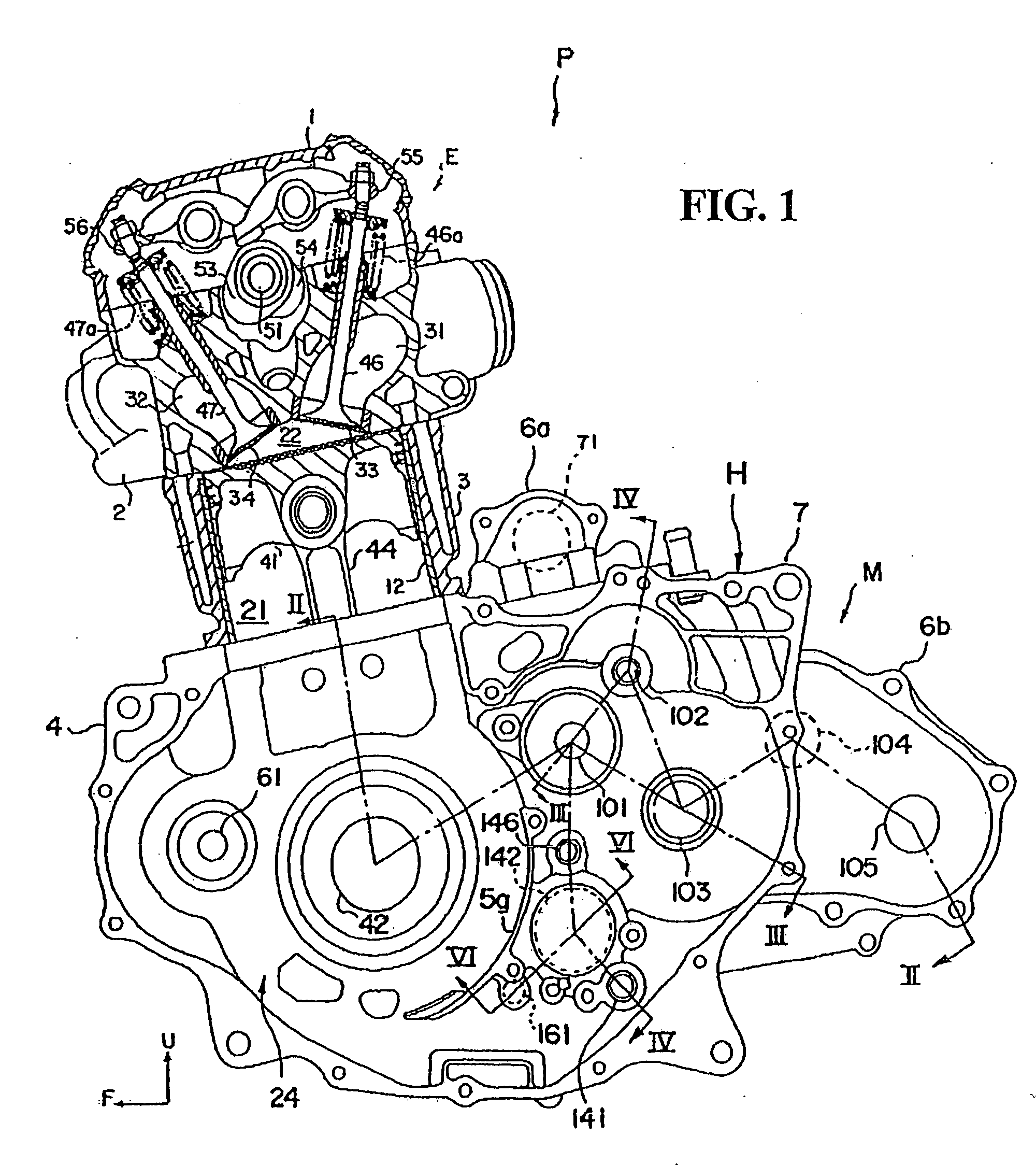
[0032]Selected illustrative embodiments of the invention will now be described in some detail, with reference to the drawings. It should be understood that only structures considered necessary for clarifying the present invention are described herein. Other conventional structures, and those of ancillary and auxiliary components of the system, are assumed to be known and understood by those skilled in the art. In the figures, arrows U and F denote the upper side and front, respectively, and references to left and right directions are made with respect to the front.

[0033]FIG. 1 is a cross-sectional view of a power unit P of a saddle-ride type vehicle as viewed from the left side, the power unit being provided with a lubricating device according to the present invention. Saddle-type vehicles are characterized by a seat which is straddled by the vehicle operator. Examples of saddle-ride type vehicles include, but are not limited to, four-wheeled all-terrain vehicles, motorcycles, and j...


PUM


Abstract

A power unit of a vehicle, which includes an internal combustion engine and a transmission, is provided which is configured to quickly return lubricating oil fed to the transmission to an oil storage portion of the power unit case. The transmission includes a gear train housed in a gear chamber, the gear train executing power transmission among an input shaft, an intermediate shaft and an output shaft. The input shaft and the output shaft are arranged such that a line connecting their respective shaft centers extends almost horizontally above a communicating port which permits return oil flow between segregated portions of the power unit case. In addition, the intermediate shaft is disposed above and between the input shaft and the output shaft.

Description

CROSS-REFERENCE TO RELATED APPLICATIONS[0001]The present invention claims priority under 35 USC 119 based on Japanese patent application No. 2006-146731, filed on May 26, 2006. The subject matter of this priority document is incorporated by reference herein.BACKGROUND OF THE INVENTION[0002]1. Field of the Invention[0003]The present invention relates to a vehicle power unit, the power unit including an internal combustion engine and a transmission, the transmission modifying the rotational speed of the engine and transmitting the rotational driving force of the engine to vehicle wheels.[0004]2. Description of the Background Art[0005]In a known a vehicle power unit, which includes an internal combustion engine and a transmission, the transmission is configured to include input and output shafts disposed parallel to each other, and to further include a plurality of gear trains arranged between the input and output shafts. Such a power unit is disclosed, for example, in Japanese Patent ...

Claims


Application Information

Patent Timeline
IPC IPC(8): F16C11/00F16H57/02B60K5/00B60K17/08
CPCF01M11/02F02B61/02F16H57/02F16H57/04Y10T74/19219F16H2057/02065Y10T74/2186Y10T74/2185Y10T74/2189F16H2057/0203
Inventor NISHI, TORUMOHARA, TOSHINARI
Owner HONDA MOTOR CO LTD
Why Eureka
Try Eureka