Apparatus and method for cleaning stencils employed in a screen printing apparatus

a screen printing apparatus and stencil cleaning technology, applied in the field of screen printing apparatuses, can solve the problems of affecting the precision and affecting the quality of screen printing stencils,

Inactive Publication Date: 2007-12-27
IBM CORP
View PDF4 Cites 16 Cited by
  • Summary
  • Abstract
  • Description
  • Claims
  • Application Information

AI Technical Summary

Benefits of technology

[0007] Accordingly, it is an object of the present invention to provide an improved method of cleaning a printing stencil employed in printing app

Problems solved by technology

The complexity and compactness of present day electronic products requires increased packing density of various conductive circuit configurations on the surface of substrates, circuit boards, and other components.
However, the precision of such printed patterns is often compromised by paste material and other debris accumulating on the stencil surface that contacts the surface of the component being printed.
Although these cleaning steps do remove some or even most of the paste residue from the printing face of the stencil they leave slight amounts of residue or debris on its printing surface of the stencil.
After a number of substrates are printed it has been found such residue builds up and hard

Method used


Image

  • Apparatus and method for cleaning stencils employed in a screen printing apparatus
  • Apparatus and method for cleaning stencils employed in a screen printing apparatus
  • Apparatus and method for cleaning stencils employed in a screen printing apparatus

Examples


Embodiment Construction

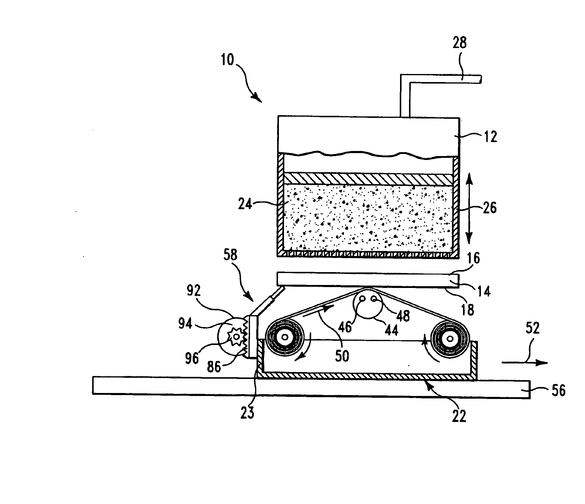
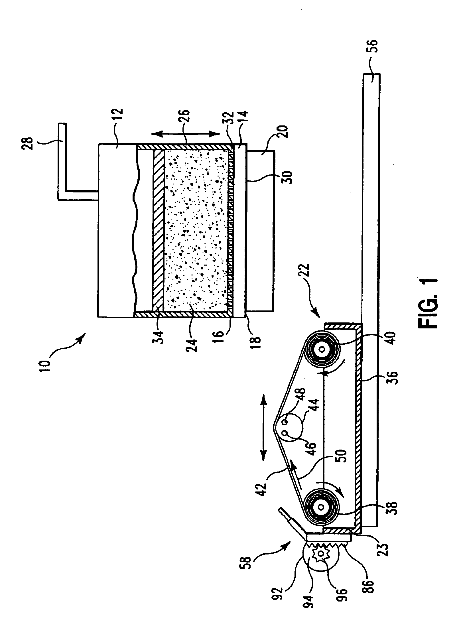
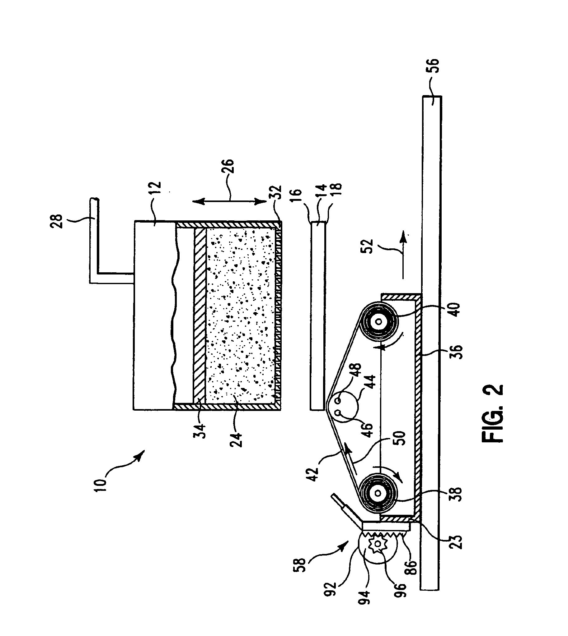
[0017] The preferred embodiment of the invention will now be described, with regard to the figures wherein: FIG. 1 is a diagrammatic sectional view of the stencil printing apparatus of a preferred embodiment of the invention FIG. 2 is a view of the printing apparatus depicted in FIG. 1; FIG. 3 is an enlarged exploded view in perspective of the elements of the cleaning blade assembly shown in FIGS. 1 and 2; FIG. 4 is an enlarged view in perspective of the cleaning blade assembly illustrated in FIG. 3; and FIG. 5 is a view of the preferred embodiment printing apparatus of the invention illustrating a cleaning cycle utilizing the blade assembly in accordance with the invention.

[0018]FIG. 1 is a diagrammatic cross-sectional view of a printer apparatus 10 and comprises: a paste dispensing head 12; a stencil 14 having an upper and lower surface 16 and 18 respectively; a substrate 20 for receiving the paste in the pattern defined by the stencil; and a cleaning module 22 positioned for cle...


PUM


Abstract

A stencil printing method and apparatus for printing paste material in a given pattern on a substrate from a paste dispenser through a stencil to define the stencil pattern on a substrate. The apparatus is provided with a cleaning module that can be moved against the printing face of the stencil and moved, along a given path beneath the stencil, for cleaning the printing face of the stencil. The cleaning module includes a blade assembly mounted there on transverse to the path of movement of the cleaning module. The print apparatus further including selectively operable means for actuating the blade assembly during a select cleaning cycle to engage the leading end of its blade with the underside of the stencil as the cleaning module is passed beneath said stencil whereby the leading edge of the blade scrapes debris from the underside of said stencil. The stencil printing and cleaning method of the invention uses the steps of: dispensing a paste material through a stencil onto a substrate surface to define a given pattern thereon; and passing a cleaning module, provided with a scraping blade that can be extended above the module to contact the lower surface of the stencil to clean the underside thereof when the leading edge of the blade is in contact with the underside of the stencil.

Description

FIELD OF THE INVENTION [0001] This invention generally relates to a screen printing apparatus for fabrication of substrates, circuit boards and other electronic circuit components, and more particularly relates to a method and apparatus for cleaning the mask, or stencil, utilized in such screen printing arrangements. BACKGROUND OF THE INVENTION [0002] The complexity and compactness of present day electronic products requires increased packing density of various conductive circuit configurations on the surface of substrates, circuit boards, and other components. One method of accomplishing this is by a contact printing apparatus such as a 265 Infinity printer apparatus commercially available from DEK International of Flemington, N.J. Such machines print the desired pattern by depositing a conductive paste, such as solder paste, through a metal stencil directly onto the surface of the component. However, the precision of such printed patterns is often compromised by paste material and...

Claims


Application Information

Patent Timeline
IPC IPC(8): B41F35/00
CPCB41F35/005H05K3/1233H05K2203/0139H05K2203/0126H05K3/26
Inventor DE SOUSA, ISABELRIEL, ROBERTTESSIER, NICOLASTREMBLAY, JOEL
Owner IBM CORP
Why Eureka
Try Eureka