
Phase angle detection apparatus and variable valve timing control apparatus using the phase angle detection apparatus for internal combustion engine

a phase angle detection and control apparatus technology, applied in mechanical devices, machines/engines, valve arrangements, etc., can solve the problems of difficult to precisely execute the phase control by only the cam angle and crank angle sensors, and difficult to detect the relative rotational phase difference by the cam angle sensor

Inactive Publication Date: 2007-12-27
HITACHI LTD
View PDF2 Cites 11 Cited by
  • Summary
  • Abstract
  • Description
  • Claims
  • Application Information

AI Technical Summary

Benefits of technology

[0011]It is therefore an object of the present invention, to provide a phase angle detection apparatus which is capable of detecting the rotational phase difference between at least two rotary members with high precision.

Problems solved by technology

In this case where the curvature of the outer end side of the spiral guide is changed around the most-retarded rotational angle side, when the electromagnetic brake is applied from the engine start-up, since both a retardation control and an advancement control are continuously carried out, it is difficult to detect the relative rotational phase difference by the cam angle sensor and the crank angle sensor.
That is to say, since the rotational phase of the camshaft shifts to different directions, i.e. in the retarded phase direction and the advanced phase direction, by way of the same electromagnetic brake application by the energization, it is difficult to precisely execute the phase-control by only the cam angle and crank angle sensors.

Method used


Image

  • Phase angle detection apparatus and variable valve timing control apparatus using the phase angle detection apparatus for internal combustion engine
  • Phase angle detection apparatus and variable valve timing control apparatus using the phase angle detection apparatus for internal combustion engine
  • Phase angle detection apparatus and variable valve timing control apparatus using the phase angle detection apparatus for internal combustion engine

Examples


Embodiment Construction

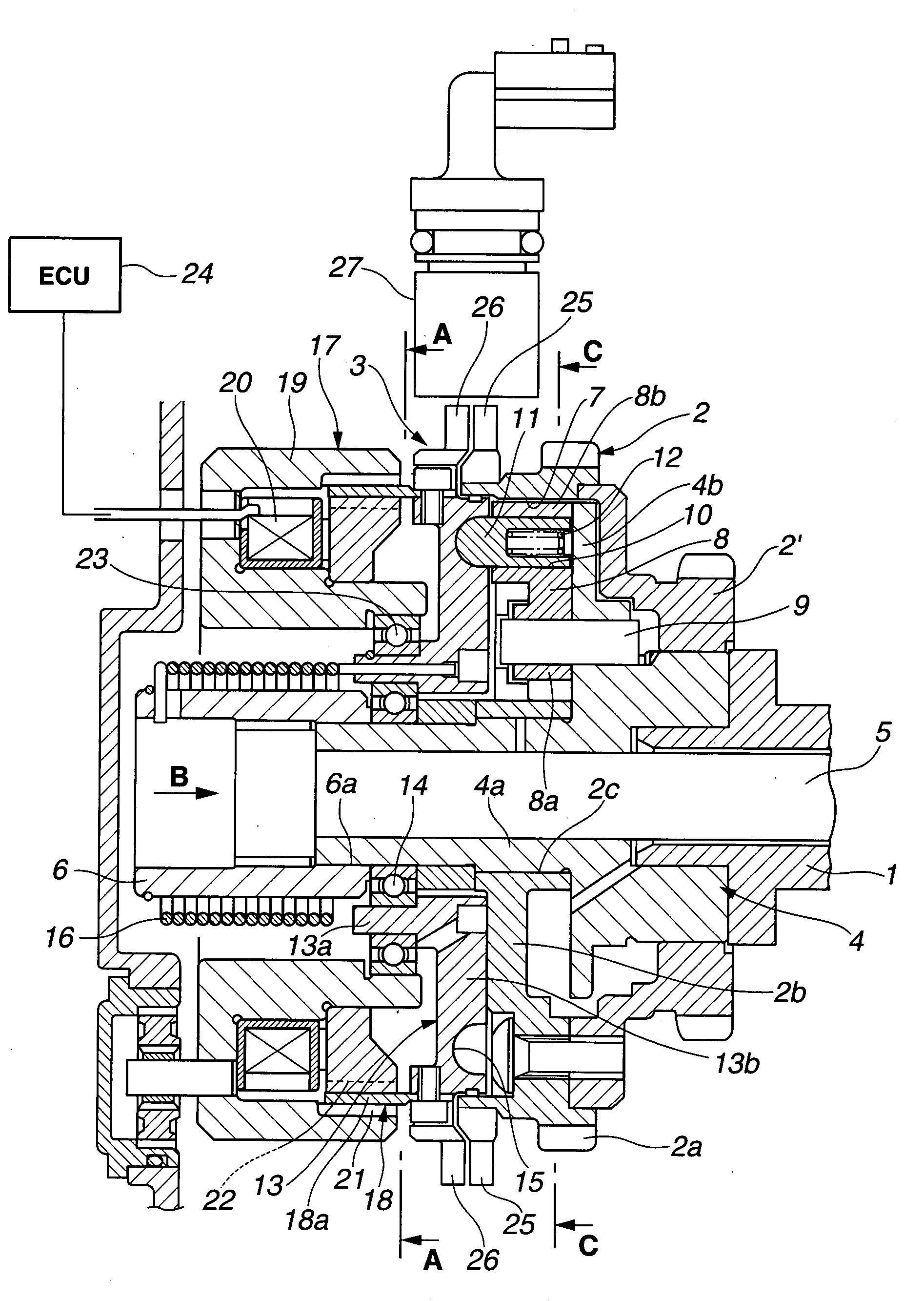
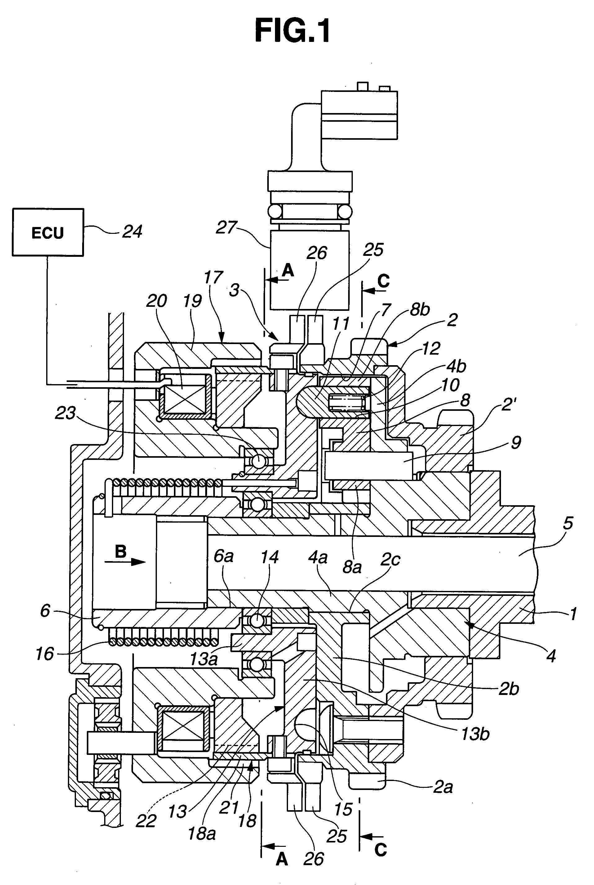
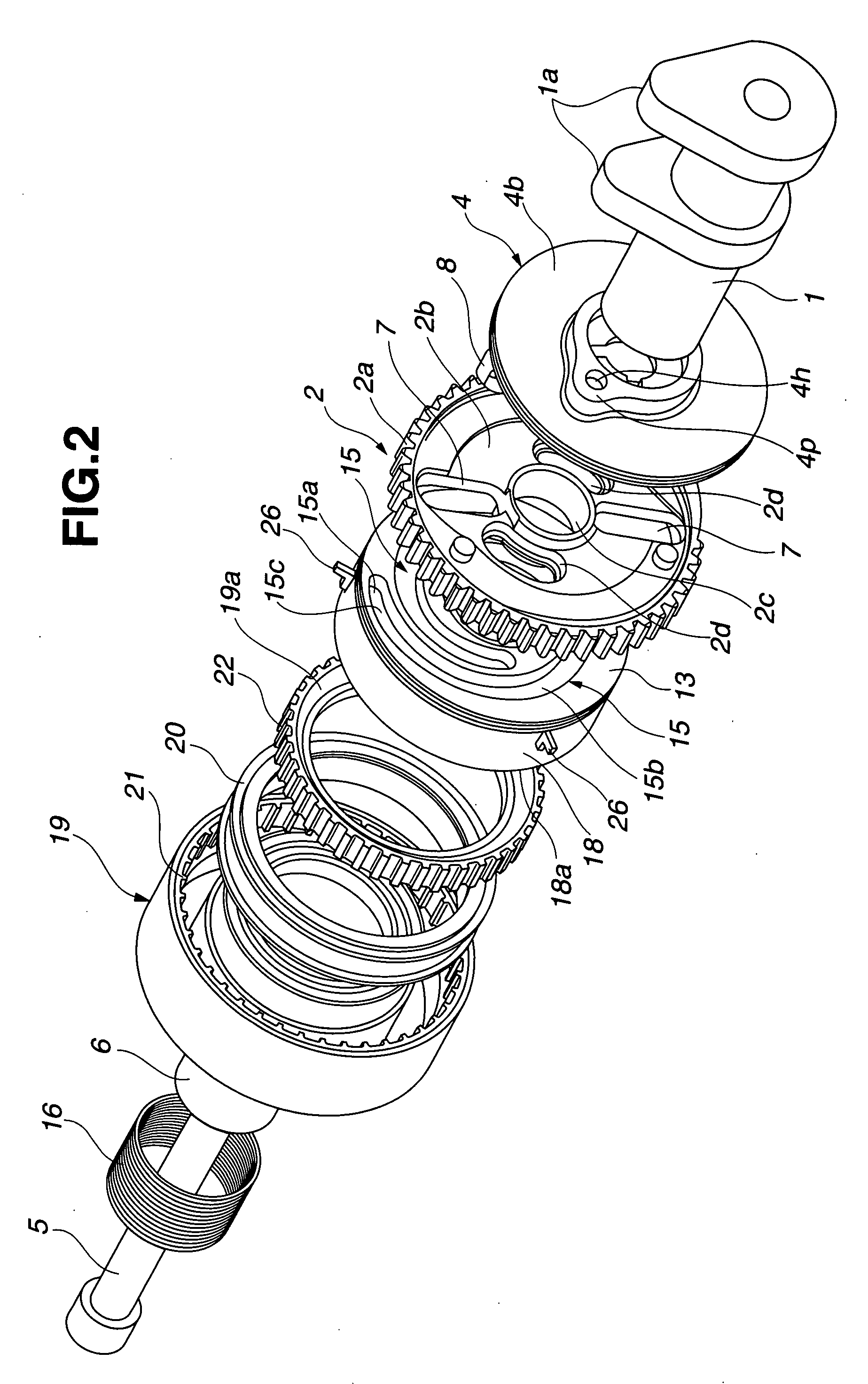
[0029]Embodiments of a phase angle detection apparatus applied to a variable valve timing control apparatus of an internal combustion engine will be explained below with reference to the drawings. In the following description, the terms “front” and “rear” are used for purposes of locating one element relative to another and are not to be construed as limiting terms. And in FIGS. 2 and 3, “front side” is a side of a torsion spring 16 (described later), and “rear side” is a side of a cam 1a (also described later). Further, although each embodiment below is applied to control of open / close timing of an intake valve for the internal combustion engine, it can also be applied to control of open / close timing of an exhaust valve.

[0030]Firstly, the variable valve timing control apparatus using the phase angle detection apparatus will be explained with reference to FIGS. 1 to 9. The variable valve timing control apparatus includes a camshaft 1 rotatably supported on a cylinder head (not shown...


PUM


Abstract

A phase angle detection apparatus includes an intermediate rotary member changing an operating angle of a driven member that is driven by a driving member, a detection unit detecting a rotational angle of the intermediate rotary member, which corresponds to the operating angle of the driven member, and outputting the rotational angle as a detection pulse signal, a controller receiving the detection pulse signal and calculating a pulse rising time difference between the detection pulse signal and a pre-set reference pulse signal. The controller detects, based on the pulse rising time difference, a predetermined middle angle position of the driven member from all the operating angles of the driven member.

Description

BACKGROUND OF THE INVENTION[0001]The present invention relates to a phase angle detection apparatus that detects a rotational phase difference between at least two rotary members, and more particularly to a phase angle detection apparatus which is used for a variable valve timing control apparatus of an internal combustion engine, which variably controls open / close timing of an intake-side or exhaust-side valve of the internal combustion engine according to an engine operating condition.[0002]In recent years, there have been proposed and developed various variable valve timing control apparatuses. One such variable valve timing control apparatus has been disclosed in Japanese Patent Provisional Publication No. 2005-180307 (hereinafter is referred to as “JP2005-180307”) corresponding to U.S. Pat. No. 7,143,730 (B2).[0003]The variable valve timing control apparatus disclosed in JP2005-180307 includes a timing sprocket to which a torque (turning force) is transferred from a crankshaft ...

Claims


Application Information

Patent Timeline
IPC IPC(8): F01L1/34
CPCF01L1/344F01L2820/041F01L1/352
Inventor KOBAYASHI, YOSHIYUKIWATANABE, MASAHIKOSAITOH, MICHINORI
Owner HITACHI LTD
Learn More