Self-tightening clamp assemblies for protection against full pipe separation

a technology of clamp assembly and full pipe separation, which is applied in the direction of fluid pressure sealing joint, flanged joint, sleeve/socket joint, etc., can solve the problems of carbon steel and low alloy steel piping weldments that are deficient in clamp types, carbonate stress corrosion cracking, leakage and cracking, etc., to achieve enhanced gripping properties and increase gripping force

Active Publication Date: 2007-12-27
PHILLIPS 66 CO
View PDF25 Cites 38 Cited by
  • Summary
  • Abstract
  • Description
  • Claims
  • Application Information

AI Technical Summary

Benefits of technology

[0006]It is, therefore, an object of the invention to provide improved clamp assemblies and clamping methods designed for application to the joint between pipe sections, in order to provide a more effective clamping action even in the event of relative separation movement between the pipes.
[0008]It is yet another object of the invention to provide improved clamp assemblies and methods wherein the assemblies are equipped with pipe-engaging teeth oriented against separation movement of the engaged pipes and further having mechanical advantage geometries which create increased gripping forces as a result of relative separation movement between clamped pipes.

Problems solved by technology

Such pipe sections are subject to varying temperature and pressure conditions which can lead to failures, particularly at the welded pipe joints.
One such failure mechanism is referred to as carbonate stress corrosion cracking, which is a common problem within fluid catalytic cracking units, especially in the main fractionator overhead condensing and reflux systems, the downstream wet gas compression systems, and the sour water systems emanating from the foregoing.
Carbonate stress corrosion cracking results in leakage and cracking in carbon steel and low alloy steel piping weldments if appropriate post-weld heat treatment is not adequately performed.
These types of clamp are deficient, however, inasmuch as they do not provide any self-tightening feature which causes the clamp to effect a tighter gripping relationship with the pipe sections as the latter tend to separate.
However, these units do not include separable clamp bodies, and thus cannot be applied to continuous piping around existing joints.

Method used


Image

  • Self-tightening clamp assemblies for protection against full pipe separation
  • Self-tightening clamp assemblies for protection against full pipe separation
  • Self-tightening clamp assemblies for protection against full pipe separation

Examples


Embodiment Construction

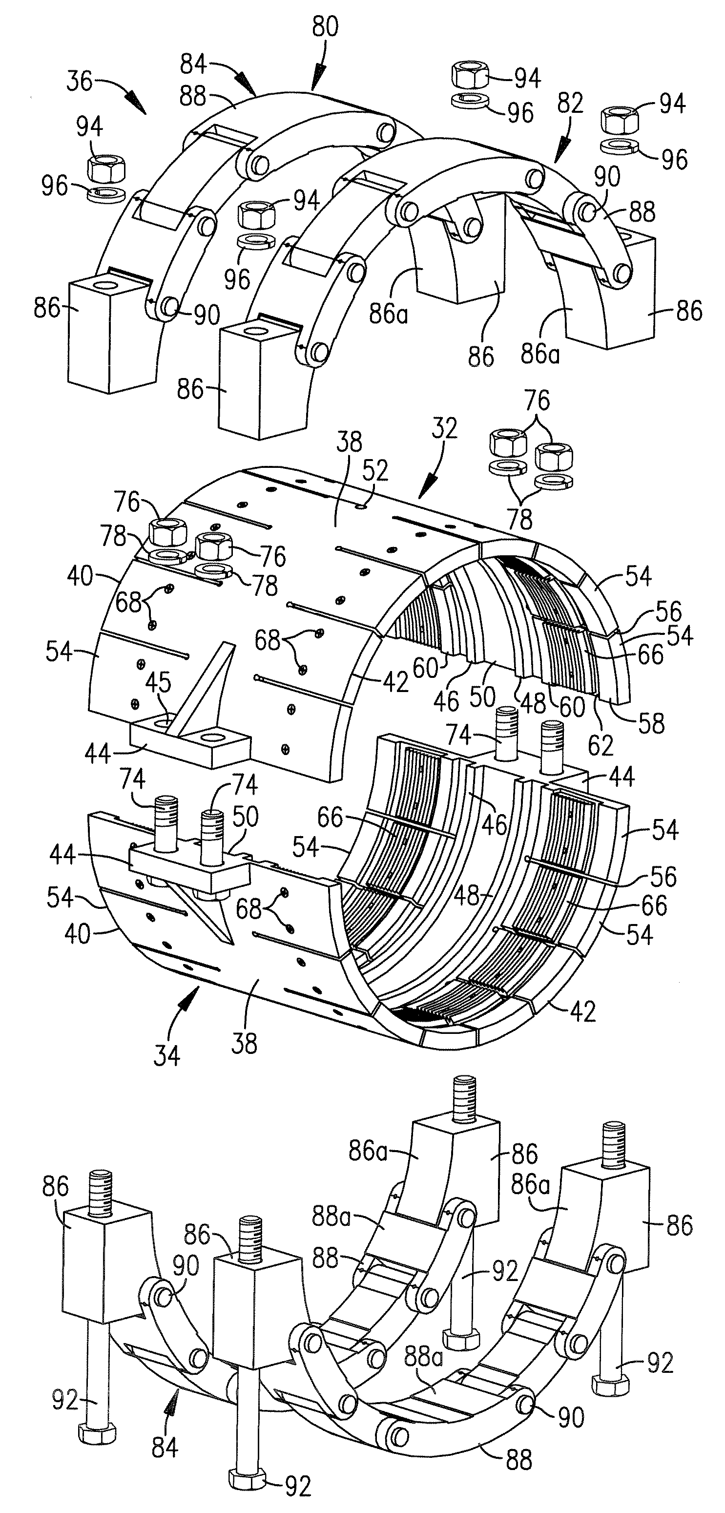
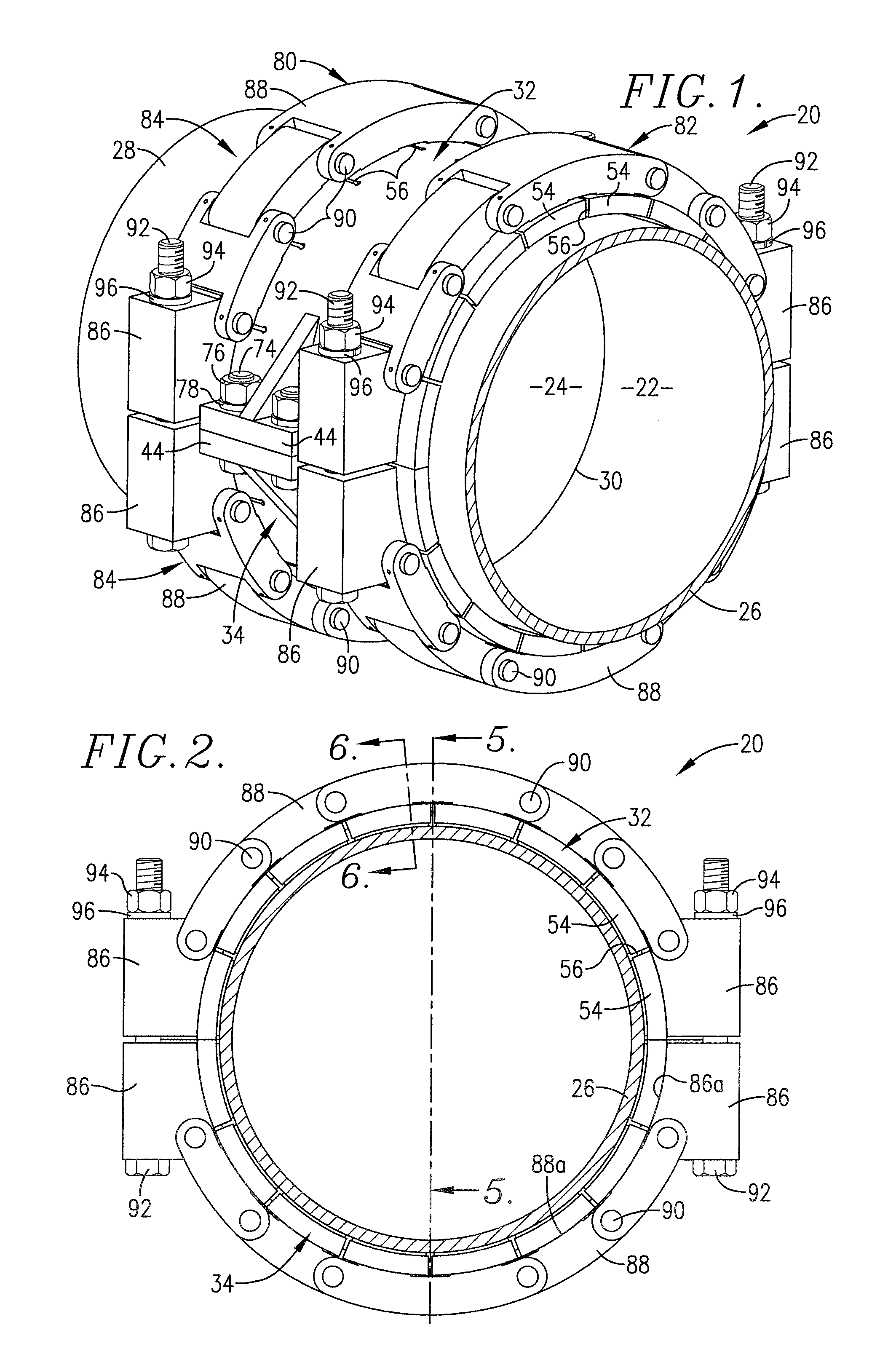
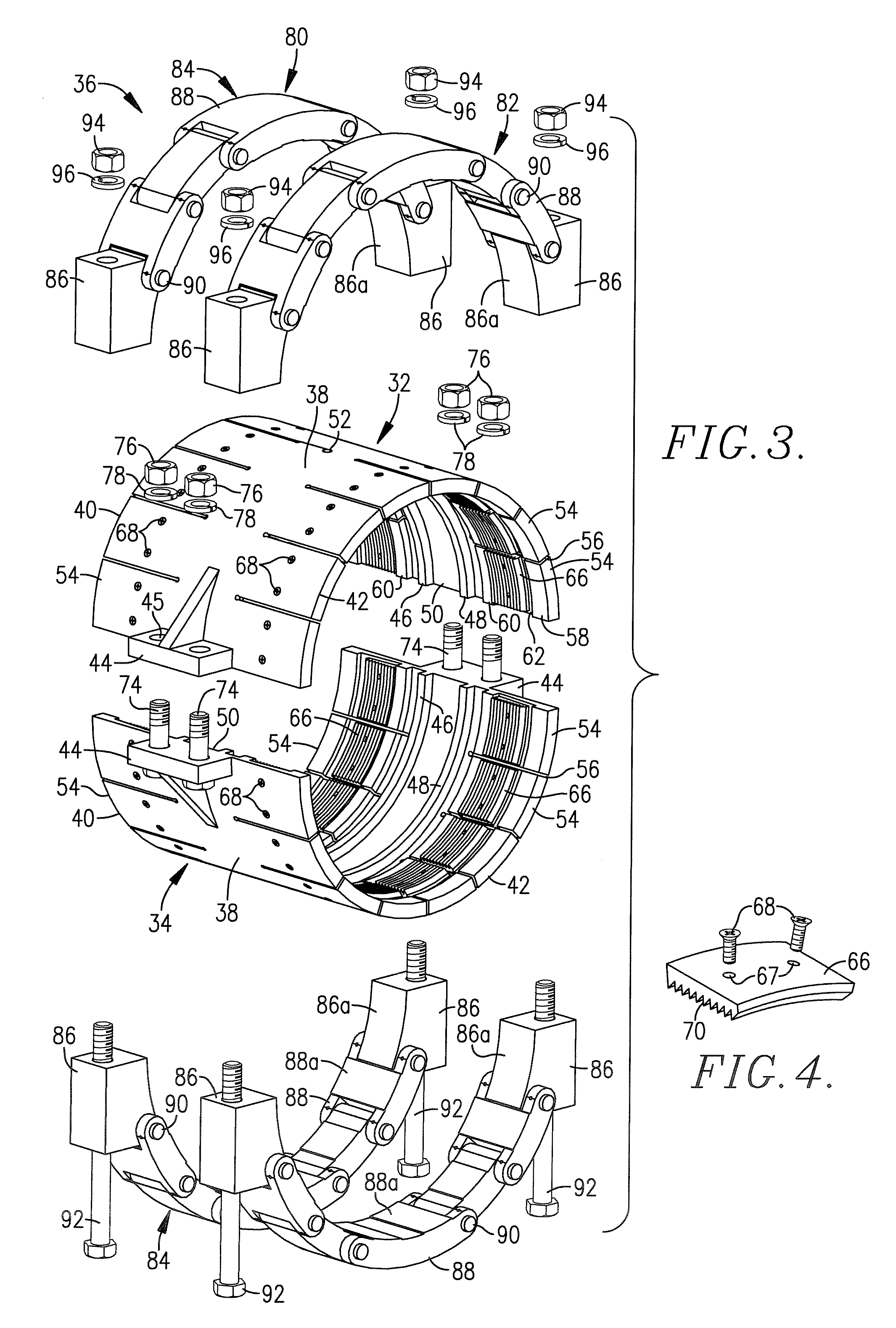
[0026]Turning now to the drawings, particularly FIGS. 1-7, a self-tightening clamp assembly 20 is depicted. The assembly 20 is designed for installation about the adjacent ends 22,24 of a pair of elongated pipe sections 26,28, and specifically in bridging relationship to the weld joint 30 between the ends 22,24. Broadly speaking, the assembly 20 includes a pair of clamp bodies 32,34 designed to cooperatively surround the ends 22,24, as well as a clamping mechanism 36 operably coupled with the clamp bodies 32,34 in order to draw the latter into tight gripping engagement with the ends 22,24.

[0027]In more detail, the bodies 32,34 are each formed of malleable metal and are substantially semi-circular in configuration and are designed for mating interconnection. Referring first to the body 32, it will be seen that it has a central body section 38 (FIG. 3) as well as side peripheral sections 40,42. The central section 38 is essentially imperforate and has endmost, external flange couplers...


PUM


Abstract

Improved self-tightening clamp assemblies are provided, which are designed for application to the adjacent ends of connected pipe sections in spanning relationship to the joint therebetween. The assemblies include a plurality of clamp bodies configured for placement about the adjacent pipe section ends and carrying a plurality of pipe-engaging teeth; a clamping mechanism is operably coupled with the clamp bodies to cause the teeth to grippingly engage the pipe section ends. The teeth are oriented so as to exert an increasing gripping force on the pipe sections ends in the event of relative separation movement between the ends.

Description

[0001]The present invention is broadly concerned with improved clamp assemblies adapted for application to the joint between welded-together pipe sections in order to prevent full separation of the pipes. More particularly, the invention pertains to clamp assemblies of this character having self-tightening capabilities, i.e., the clamp assemblies exert an increasing gripping force on the engaged pipes in the event of relative separation movement between the pipes.BACKGROUND OF THE INVENTION[0002]Piping systems in refinery and other oil and gas plants make use of welded pipe sections of various sizes. Such pipe sections are subject to varying temperature and pressure conditions which can lead to failures, particularly at the welded pipe joints. One such failure mechanism is referred to as carbonate stress corrosion cracking, which is a common problem within fluid catalytic cracking units, especially in the main fractionator overhead condensing and reflux systems, the downstream wet g...

Claims


Application Information

Patent Timeline
Patent Type & Authority Applications(United States)
IPC IPC(8): F16L25/00F16L21/02
CPCF16L55/172F16L25/12
Inventor JONES, JAMES W.SNIR, MEIRJOZAVI, HOOSHANGEVANS, HERSEHELGUZMAN, NASBILITSCHEWSKI, MIKECHA, CHRISLARSON, RICK
Owner PHILLIPS 66 CO
Why Eureka
Try Eureka