Method and Apparatus for Controlling a Magnetic Bearing Device

a magnetic bearing and control scheme technology, applied in the direction of bearings, shafts, dynamo-electric machines, etc., can solve the problems of inability to achieve good control schemes in controlling tilting motions, failure to achieve good control schemes in prior art, and failure to achieve stable control at high rotation frequency. achieve the effect of stable control of a magnetic bearing devi

Inactive Publication Date: 2007-12-27
MECOS
View PDF12 Cites 13 Cited by
  • Summary
  • Abstract
  • Description
  • Claims
  • Application Information

AI Technical Summary

Benefits of technology

[0014] It is therefore an object of the present invention to provide a method and apparatus for controlling a magnetic bearing device which enables stable contro...

Problems solved by technology

Excitation of the other five degrees of freedom is undesired.
However, for rapidly rotating rotors, such a control scheme often does not achieve good results in controlling the tilting motions.
However, the control schemes of the prior art still often fail to achieve good, stable control at high rotat...

Method used


Image

  • Method and Apparatus for Controlling a Magnetic Bearing Device
  • Method and Apparatus for Controlling a Magnetic Bearing Device
  • Method and Apparatus for Controlling a Magnetic Bearing Device

Examples


Embodiment Construction

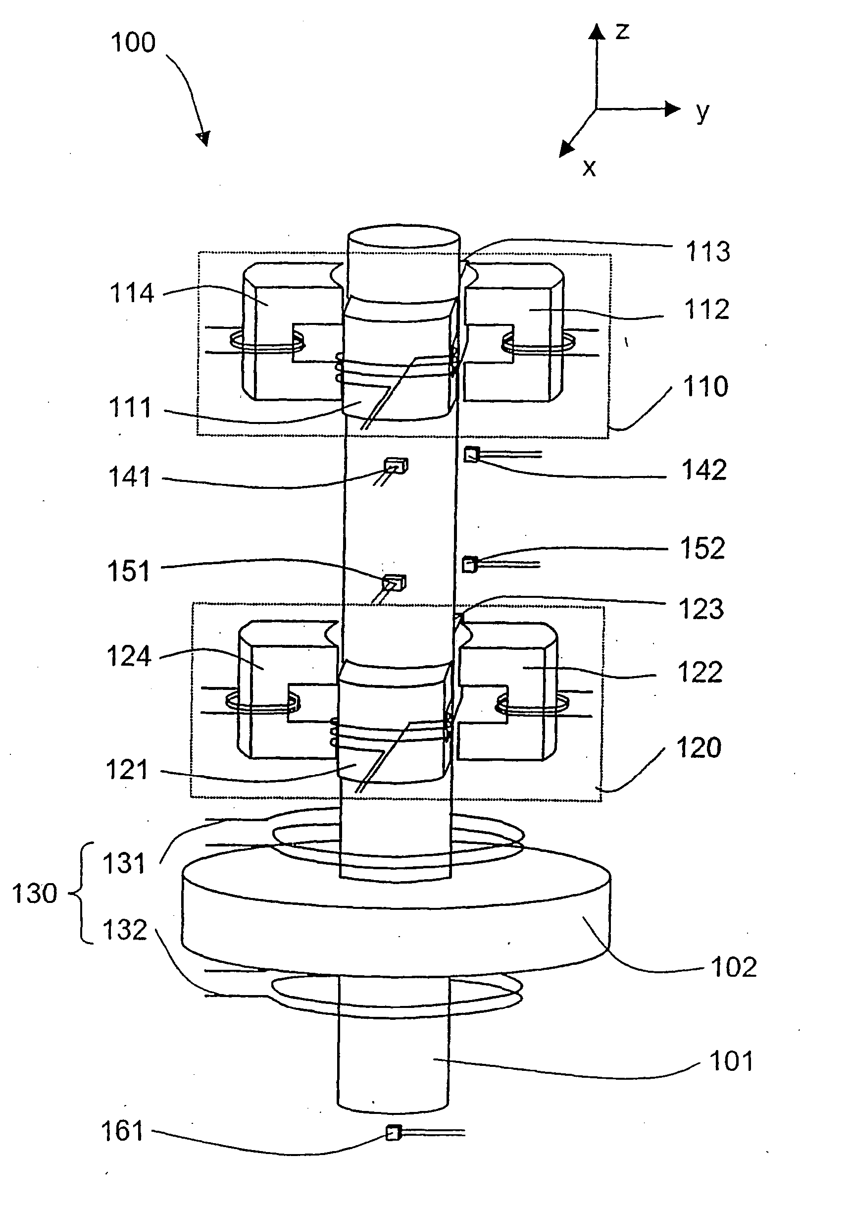
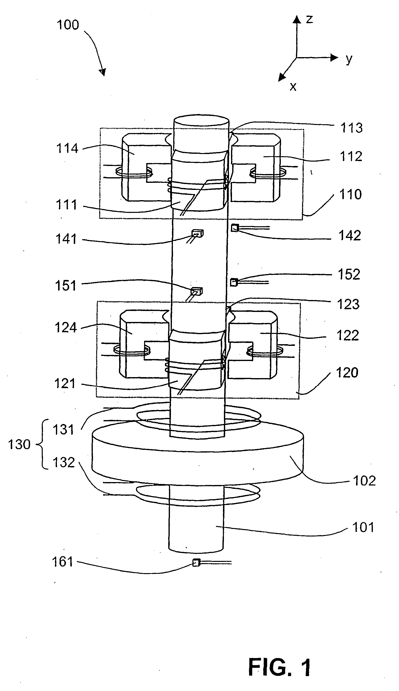
[0061] First, some features of a magnetic bearing device will be explained by way of example with reference to FIG. 1. This figure shows, in a highly schematic manner, a rotor shaft 101 suspended in a magnetic bearing device 100 for rotation about the z direction. Attached to the rotor shaft may be a rotor body carrying, e.g. rotor blades for use in a TMP, which is not shown in FIG. 1. The bearing device comprises a first (upper) radial bearing unit 110, a second (lower) radial bearing unit 120, and an axial (thrust) bearing unit 130 cooperating with a disk 102 attached to the shaft 101. The upper radial bearing unit 110 comprises four actuators 111, 112, 113, and 114 for exerting forces on an upper region of the shaft 101 in the +x, +y, −x, and −y directions, respectively, the x and y directions being mutually orthogonal and perpendicular to the z direction. Likewise, the lower radial bearing unit 120 comprises four actuators 121, 122, 123, and 124 for exerting forces on a lower re...


PUM


Abstract

A method and a controller for controlling a magnetic bearing device, in which a rotor is suspended for rotation around a shaft, are disclosed. Sensor signals are transformed to yield tilt displacement signals (Sθx, Sθy) which correspond to tilting displacements of the shaft in predetermined directions (x, y). From the tilt displacement signals (Sθx, Sθy), tilt control signals Aθx, Aθy) are derived; these are transformed to yield actuator control signals for driving electromagnetic actuators in the magnetic bearing device. According to the invention, tilting displacements for which the tilt vector rotates about the device axis (z) with a first predetermined sense of rotation are controlled separately from tilting displacements for which the tilt direction vector rotates about the device axis (z) with a second sense of rotation opposite to the first predetermined sense of rotation. In this way, control of nutation and precession can be achieved without influence from blade vibrations or shaft bending modes.

Description

FIELD OF THE INVENTION [0001] The present invention relates to the control of a magnetic bearing device, in which a rotor is suspended for rotation about a rotation axis. Specifically, the present invention relates to a method for controlling a magnetic bearing device according to the preamble of claim 1 and to a controller for such a bearing device according to the preamble of claim 5. Furthermore, the invention relates to a magnetic bearing device according to claim 11 and a turbo-molecular pump according to claim 12. BACKGROUND OF THE INVENTION [0002] Magnetic bearings are useful in a variety of applications in which a rotor is to be rotated in a contact-free manner. Applications of magnetic bearings include, e.g., turbo-molecular pumps (TMPs). [0003] A rotor suspended in a magnetic bearing device for rotation around a rotor shaft can be described, to a first approximation, as a rigid object having six spatial degrees of freedom (DOFs). One DOF is the rotation around the device a...

Claims


Application Information

Patent Timeline
IPC IPC(8): G05B1/02F04B17/03H02K7/09F16C39/06
CPCF16C32/0442F16C2360/45F16C32/0455F16C32/0453
Inventor BUHLER, PHILIPPLARSONNEUR, RENE
Owner MECOS
Why Eureka
Try Eureka