Rear Projection Screen and Associated Display System

a display system and projection screen technology, applied in the field of projection screen, can solve the problems of loss of resolution in the direction of parallax provided, and loss of luminance/brightness of around 50%

Inactive Publication Date: 2007-12-27
MICROSHARP CORP LTD
View PDF11 Cites 42 Cited by
  • Summary
  • Abstract
  • Description
  • Claims
  • Application Information

AI Technical Summary

Benefits of technology

[0019] Autostereoscopic display systems currently on the market use a set resolution display and a parallax barrier along one dimension, which leads to a loss in resolution in the direction in which parallax is provided and also a loss in luminance / brightness of around 50%. The display system of the present invention is easily scalable to large display sizes and does not suffer from the disadvantages due to loss of brightness or resolution normally encountered by direct-view parallax barrier LCD display systems. In fact, it is possible to increase the resolution of the display system when in 2D mode, as a result of the interleaving / multiplexing of the left and right images. It is therefore possible to run the display system of the present invention in any of three modes: a standard 2D mode, a double-resolution 2D mode, and the 3D autostereoscopic mode.
[0021] This aspect of the present invention provides the advantages of eliminating the need for a large scale rotating component and preventing consequent mechanical failure of components. In addition, there is no need to use layered LCD panels which typically attenuate a large amount of light.
[0042] anamorphic optical elements or digital signal processing elements. These elements allow a focused image at all points across the screen and reduce field distortions, like but not limited to keystone-type and cornerstone-type distortion of the image.
[0047] Preferably, said third planar facet is coated to enhance the said total internal reflection effect.

Problems solved by technology

Autostereoscopic display systems currently on the market use a set resolution display and a parallax barrier along one dimension, which leads to a loss in resolution in the direction in which parallax is provided and also a loss in luminance / brightness of around 50%.

Method used


Image

  • Rear Projection Screen and Associated Display System
  • Rear Projection Screen and Associated Display System
  • Rear Projection Screen and Associated Display System

Examples


Embodiment Construction

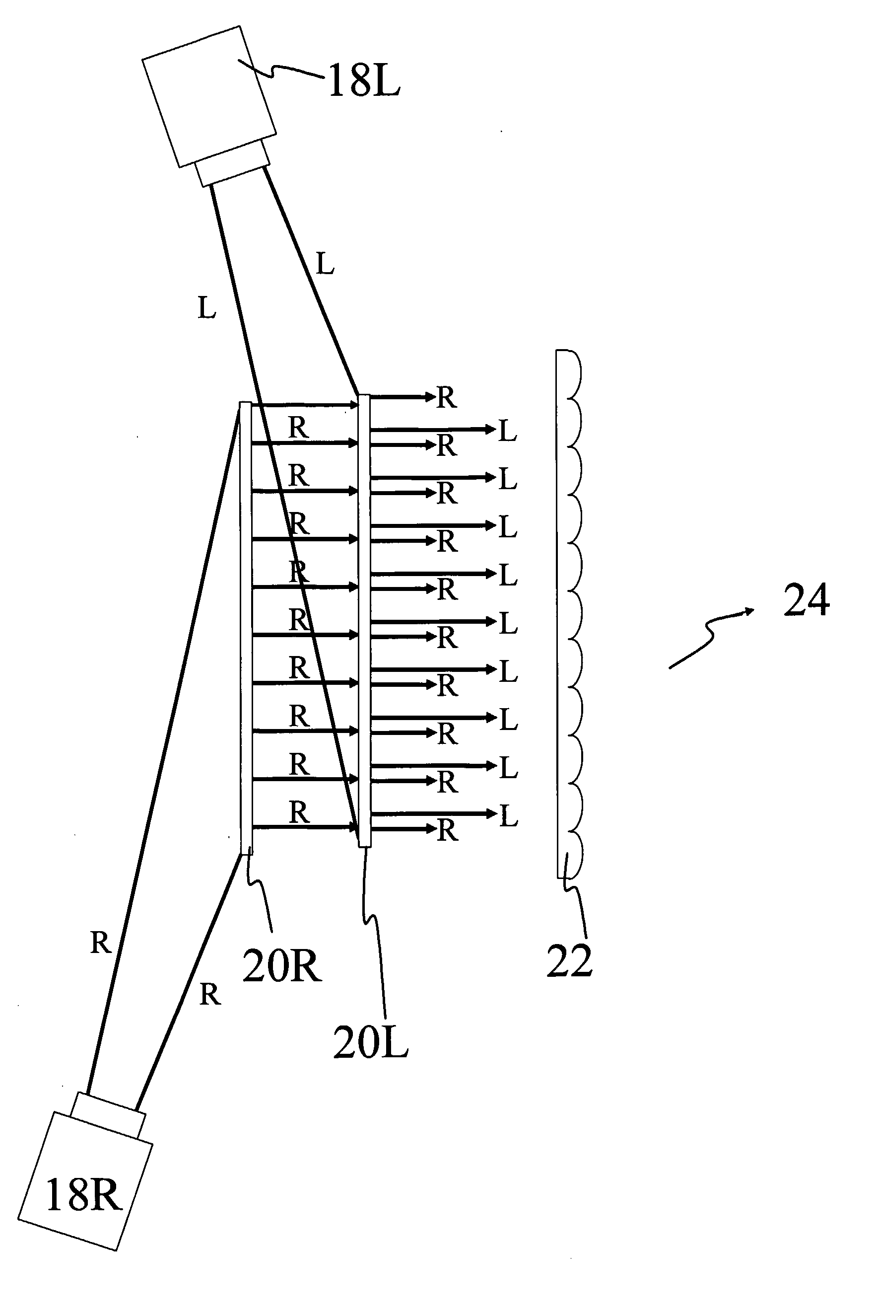
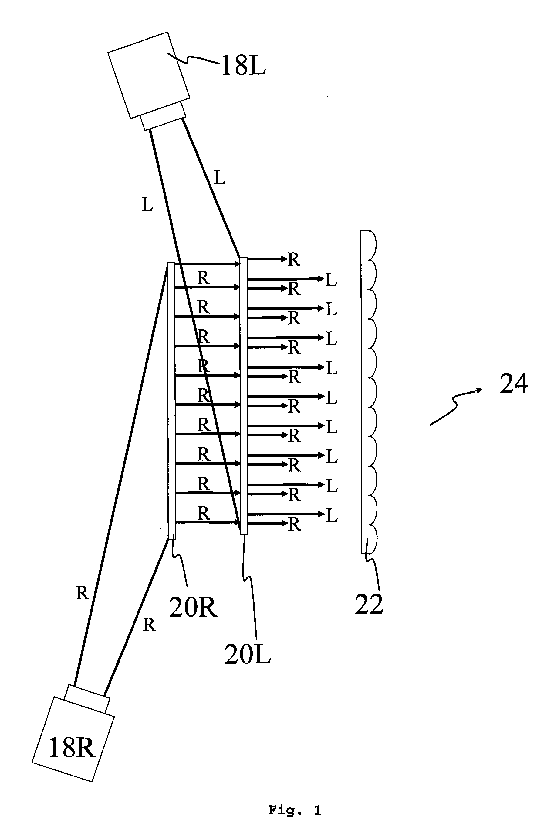
[0071] One aspect of the present invention provides a 3D display system which optically combines a right eye image with a left eye image to produce a 3D spatially multiplexed image.

[0072]FIG. 1 illustrates one preferred embodiment of a 3D rear projection display system that includes a left-image projector 18L, a right-image projector 18R, a right redirecting optical panel 20R, a left redirecting optical panel 20L, and a lenticular sheet 22. The right-eye image component generated by the right-image projector 18R is irradiated to the rear surface of the right redirecting optical panel 20R. Here, it is redirected towards the lenticular sheet 22 and a downstream viewing region 24. Thus, in addition to the optical panel 20R the redirected light also travels through the optical panel 20L, towards the lenticular sheet 22. Concurrently, the left-eye image component generated by the left-image projector 18L is irradiated to the rear surface of and then redirected by the left redirecting op...


PUM


Abstract

A rear projection display method and system, for displaying an image. The system comprises projection means ( 18 L, 18 R) to project first and second stereoscopic image components; a first light-redirecting panel ( 20 R) and a second downstream light-redirecting panel ( 20 L) to receive light representative of the first and second image components, respectively, from the projection means and to redirect that light substantially in a downstream direction, the first and second panels arranged to spatially multiplex the first and second image components; and a parallax optic element ( 22 ) located downstream of the second panel to provide at a downstream viewing zone ( 24 ) the first and second image components for autostereoscopic viewing of the image. The projection means may be switchable between 2D and 3D viewing modes. A 3D image may be produced by simultaneously or sequentially projecting a series of 2D image sections, using diffuser elements ( 45 ). A method of displaying a 3D image is also disclosed.

Description

BACKGROUND OF THE INVENTION [0001] 1. Field of the Invention [0002] The present invention relates to a display system, and more particularly to an autostereoscopic and a volumetric image display system for displaying a three-dimensional (3D) image. The present invention concerns a 3D image projection system that does not require a viewer to wear goggles or glasses. [0003] 2. Discussion of Related Art [0004] As is well known in the art, a 3D image can be obtained by combining two images, namely a left eye image and a right eye image, which are then processed through a suitable 3D display system. 3D display systems can be categorized by the technique used to channel the left and right images to the appropriate eye: those which require optical devices close to the viewer's eyes (such as glasses or goggles) are known as stereoscopic displays, while those which have the eye-addressing components completely integrated within the display itself are known as autostereoscopic displays. [0005...

Claims


Application Information

Patent Timeline
Patent Type & Authority Applications(United States)
IPC IPC(8): G03B21/00H04N13/00
CPCH04N13/0404H04N13/0409H04N13/0495H04N13/0443H04N13/0454H04N13/0411
Inventor MEZOUARI, SAMIRO'NEIL, ANNA TAYLORLEE, YONGMINKHANDAKER, IMAN IBRAHIM
Owner MICROSHARP CORP LTD
Why Eureka
Try Eureka