Stream encoder and stream decoder

Inactive Publication Date: 2007-12-27
PANASONIC CORP
View PDF7 Cites 31 Cited by
  • Summary
  • Abstract
  • Description
  • Claims
  • Application Information

AI Technical Summary

Benefits of technology

[0026]Thereby, it is possible to reproduce a multiangle stream of video data in which an overlapping portion of two pieces of video is converted into data having a small size.
[0027]According to the present invention, a plurality of channels of video are processed separately in units of ch

Problems solved by technology

However, in such a recording device, input data needs to be processed in a time-division manner so as to process the data using a single video encoder, so that motion compensation prediction cannot

Method used


Image

  • Stream encoder and stream decoder
  • Stream encoder and stream decoder
  • Stream encoder and stream decoder

Examples


Example

First Embodiment

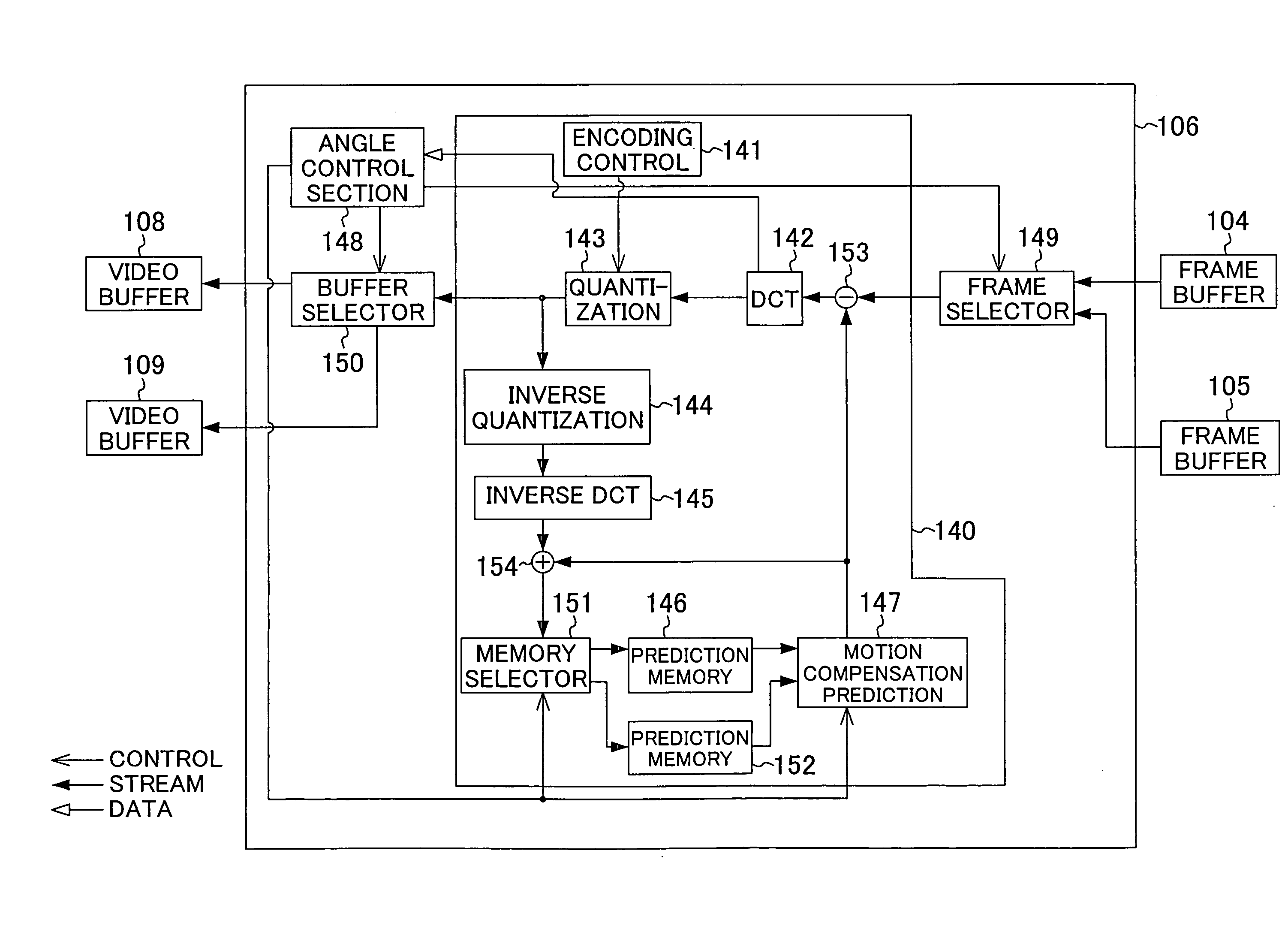
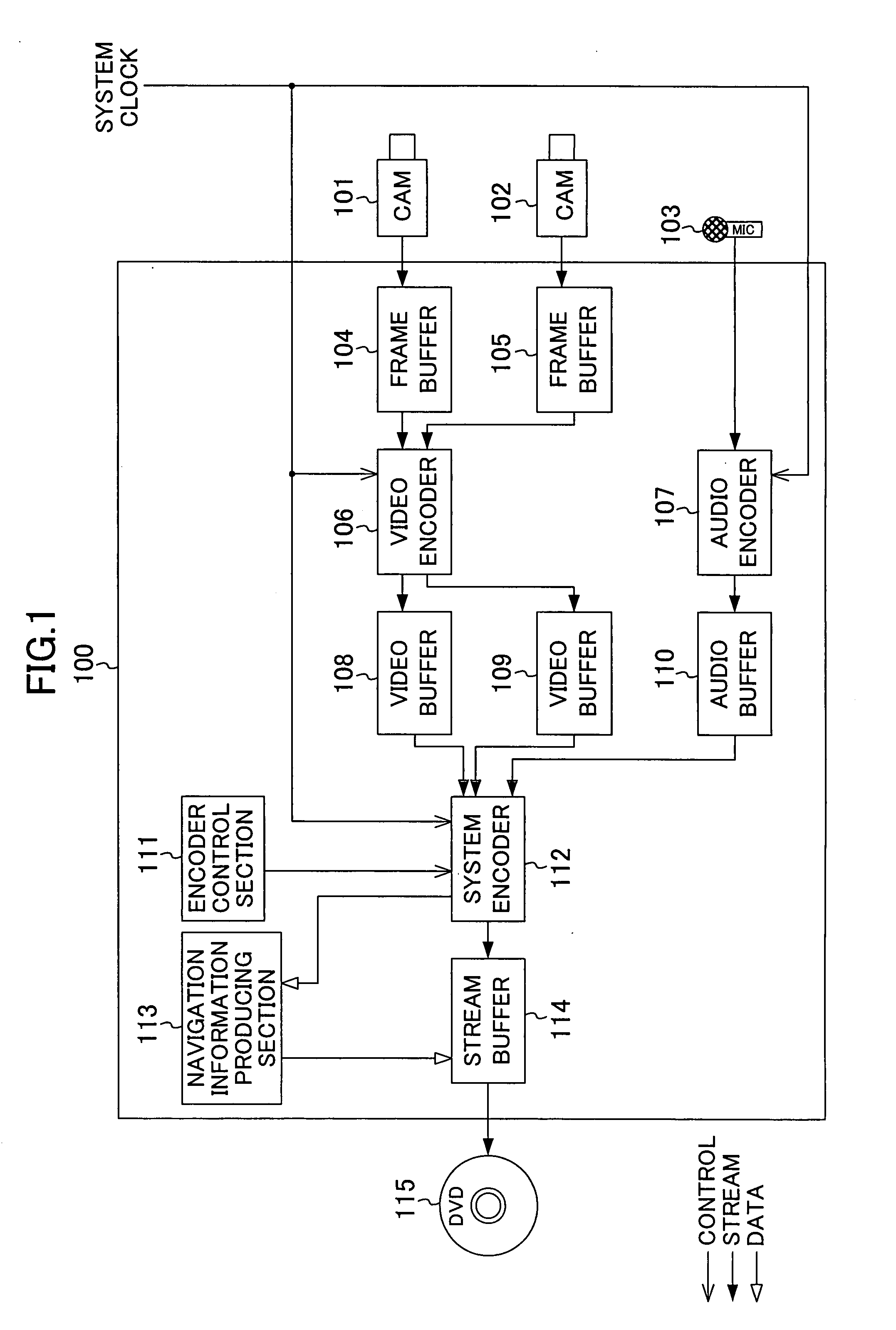
[0053]FIG. 1 is a block diagram showing a configuration of a stream encoder according to a first embodiment of the present invention. The stream encoder 100 of FIG. 1 includes frame buffers 104 and 105, a video encoder 106, an audio encoder 107, video buffers 108 and 109, an audio buffer 110, an encoder control section 111, a system encoder 112, a navigation information producing section 113, and a stream buffer 114.

[0054]The encoder control section 111 performs controls (e.g., starting and ending recording, and the like) with respect to the system encoder 112. Here, the video encoder 106 and the audio encoder 107 are assumed to be controlled in association with the system encoder 112, and the operations thereof are assumed to be performed in synchronization with the same system clock.

[0055]Cameras 101 and 102 each capture a frame of video in synchronization with video capture cycles (frame cycles) Vsync. The captured frame data is stored into the frame buffers 104 a...

Example

Second Embodiment

[0082]FIG. 7 is a block diagram showing a configuration of a system encoder 212 according to a second embodiment of the present invention. This embodiment is different from the stream encoder 100 of FIG. 1 in that the system encoder 212 is used instead of the system encoder 112. The system encoder 212 of FIG. 7 further includes a video packet header holding section 182 in addition to the configuration of FIG. 4.

[0083]The video packet generating section 162, when the first angle video encoding process is designated by the angle control section 168, generates a video packet, and at the same time, outputs a generated packet header to the video packet header holding section 182. The video packet header holding section 182 holds the packet header. The video packet generating section 162, when the second angle video encoding process is designated by the angle control section 168, uses the packet header held by the video packet header holding section 182 without newly gene...

Example

Third Embodiment

[0086]A stream encoder according to a third embodiment of the present invention will be hereinafter described. In the stream encoder of the first embodiment, when the two cameras perform shooting in the same direction from the same position, two pieces of video output from the two cameras overlap each other. In the third embodiment, one of the overlapping portions of the two pieces of video is converted into video having no motion before being recorded, thereby reducing the load of an encoding process.

[0087]FIG. 8 is a block diagram showing a configuration of the stream encoder of the third embodiment of the present invention. The stream encoder 200 of FIG. 8 is different from the stream encoder 100 of FIG. 1 in which a navigation information producing section 202 is provided instead of the navigation information producing section 113, and an overlapping video converting section 201 and a camera control section 206 are further provided.

[0088]Cameras 101 and 102 perfo...


PUM


Abstract

A stream encoder includes a video encoder for receiving and encoding first and second angle video data, and outputting the results as first and second encoded video data, a first video buffer for storing the first encoded video data, and a second video buffer for storing the second encoded video data. The video encoder includes a motion compensation prediction encoder which can encode two or more frames per frame cycle of the first or second angle video data.

Description

CROSS REFERENCE TO RELATED APPLICATIONS[0001]This Non-provisional application claims priority under 35 U.S.C. §119(a) on Patent Application No. 2006-171332 filed in Japan on Jun. 21, 2006, the entire contents of which are hereby incorporated by reference.BACKGROUND OF THE INVENTION[0002]The present invention relates to a device for generating or decoding stream data of a plurality of pieces of video.[0003]Consumer camcorders have been commonly used. Among other things, DVD (digital versatile disc) camcorders have rapidly become widespread in recent years. A multiangle function is defined in the DVD-Video standard, which is a standard for a DVD recording technique. According to the standard, video is recorded at a plurality of camera angles, and the user can freely select an angle to perform reproduction.[0004]To generate stream data used in the multiangle function, it is necessary to use a specific authoring tool to process a plurality of streams captured separately by the camcorder...

Claims


Application Information

Patent Timeline
IPC IPC(8): H04N7/12H04N5/92G11B20/10H04N19/423H04N19/46H04N19/50H04N19/513H04N19/625H04N19/70
CPCH04N5/44508H04N21/440263H04N5/85H04N9/8042H04N9/8205H04N19/597H04N19/176H04N19/70H04N19/51H04N19/61H04N19/17H04N19/85H04N21/21805H04N21/23418H04N21/2343H04N21/234336H04N21/234381H04N21/23614H04N21/2365H04N21/242H04N21/42646H04N21/431H04N21/4316H04N21/4347H04N21/4348H04N5/772H04N21/434
Inventor MIZOBUCHI, TOMOKINAGAHARA, KOSAKUKUSAKABE, TOMOAKIGOTO, OSAMUHIGUCHI, TOSHIO
Owner PANASONIC CORP
Why Eureka
Try Eureka