Automatic transmission control apparatus

a transmission control and automatic technology, applied in mechanical devices, transportation and packaging, gear trains, etc., can solve the problems of increasing possibility, increasing the possibility, and the input shaft rotation speed of the transmission may not be directly detected by a rotary-speed sensor, so as to achieve the effect of ensuring the detection of speed

Active Publication Date: 2007-12-27
JATCO LTD +1
View PDF7 Cites 28 Cited by
  • Summary
  • Abstract
  • Description
  • Claims
  • Application Information

AI Technical Summary

Benefits of technology

[0010]In view of the above-mentioned problem, one object of the present invention is to secure detection of a

Problems solved by technology

However, in recent years, multistage automatic transmissions have become more advanced with a more complicated gear train.
Thus, there is an increasing possibility that a rotation speed of an input shaft of the transmission may not be directly detected by a rotary-speed sensor.
If the speed of a transmission input shaft is not directly detected, there is a problem that even if an attempt is made to perform various kinds of control requiring gear ratio information as necessary information using an input shaft speed information and a gear ratio information using the input shaft speed information, high precision control cannot be expected.
However, if the automatic transmission fails and presents a neutral state due to disengagement by mistake of a frictionally engaging element, comparing the real gear ratio to the instructed gear ratio makes it impossible to determine the frictionally engaging element which causes the automatic transmissio

Method used


Image

  • Automatic transmission control apparatus
  • Automatic transmission control apparatus
  • Automatic transmission control apparatus

Examples


Embodiment Construction

[0024]Selected embodiments of the present invention will now be explained with reference to the drawings. It will be apparent to those skilled in the art from this disclosure that the following descriptions of the embodiments of the present invention are provided for illustration only and not for the purpose of limiting the invention as defined by the appended claims and their equivalents.

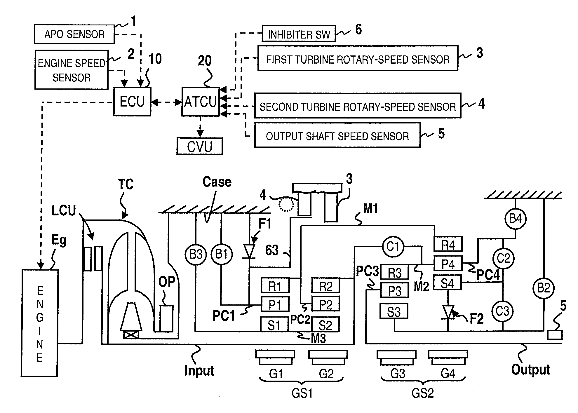
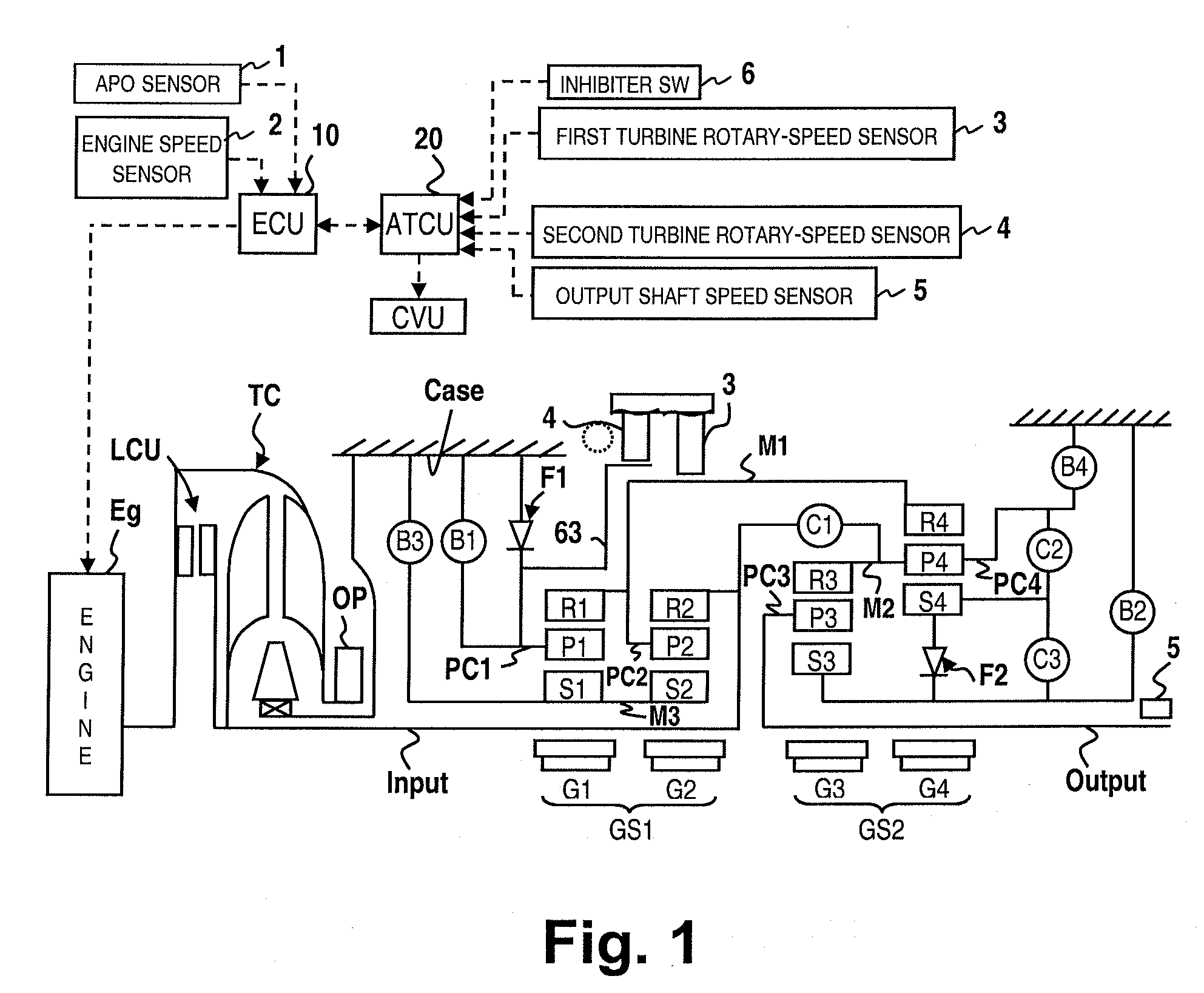
[0025]Referring initially to FIG. 1, an automatic transmission is schematically illustrated in accordance with a first embodiment of the present invention. FIG. 1 includes a skeleton view showing an automatic transmission, which a first embodiment of a control apparatus is applied to, of the type having forward 7-speed and reverse one speed, and the overall system view showing the architecture of the control apparatus for the automatic transmission. The automatic transmission is connected to an engine Eg via a torque converter TC with a lock-up clutch LUC. A rotation outputted by the engine Eg rota...


PUM


Abstract

An automatic transmission control apparatus is provided with a shift control section, a first rotary-speed detecting section, a second rotary-speed detecting section and an input shaft speed calculation section. The shift control section issues instructions to selectively engage and disengage a combination of a plurality of frictionally engaging elements of a planetary gear mechanism to establish a corresponding one of a plurality of gear ratios. The first rotary-speed detecting section detects a rotational speed of a first rotary member which rotates at a different speed from an input shaft of the planetary gear mechanism. The second rotary-speed detecting section detects a rotational speed of a second rotary member which rotates at a different speed from the input shaft of the planetary gear mechanism. The input shaft speed calculation section calculates a rotational speed of the input shaft using values detected by the first and second rotary-speed detecting sections.

Description

CROSS-REFERENCE TO RELATED APPLICATIONS[0001]This application claims priority to Japanese Patent Application No. 2006-172016, filed on Jun. 22, 2006. The entire disclosure of Japanese Patent Application No. 2006-172016 is hereby incorporated herein by reference.BACKGROUND OF THE INVENTION[0002]1. Field of the Invention[0003]The present invention generally relates to an automatic transmission control apparatus. More specifically, the present invention relates to a technology of determining which one of a plurality of frictionally engaging elements in an automatic transmission is malfunctioning (e.g., mistakenly disengaged) so as to cause the automatic transmission to fail and present a neutral state.[0004]2. Background Information[0005]In a geared automatic transmission, each of the gear ratios is achieved by selectively engaging and releasing a plurality of clutches and brakes (each generically referred to as a “frictional engaging element”). In some automatic transmissions, a plane...

Claims


Application Information

Patent Timeline
IPC IPC(8): F16H59/48F16H59/08F16H59/18F16H59/38F16H59/40F16H59/42F16H61/12F16H61/68F16H61/684F16H61/686
CPCF16H3/66Y10T477/692F16H59/40F16H61/12F16H61/686F16H2059/385F16H2059/6823F16H2061/1208F16H2061/1224F16H2200/0056F16H2200/2012F16H2200/2053F16H2059/366F16H2059/706Y10S477/906F16H59/36
Inventor YONEYAMA, NOBUYUKI
Owner JATCO LTD
Why Eureka
Try Eureka