Photovoltaic module with light reflecting backskin

a photovoltaic module and backskin technology, applied in the field of solar cell modules, can solve the problems of limiting the temperature, limiting and more difficult to permanently and precisely emboss the polyester base, so as to achieve the effect of improving the power output of the modul

Inactive Publication Date: 2008-01-03
GONSIORAWSKI RONALD C +1
View PDF3 Cites 59 Cited by
  • Summary
  • Abstract
  • Description
  • Claims
  • Application Information

AI Technical Summary

Benefits of technology

[0015] The primary object of this invention is to provide a new and improved PV module having an internal reflector that improves the power output of the module.
[0028] The method also has the steps of reflecting solar radiation impinging on the facets via the transparent front cover. The light-transmitting encapsulating material and the spaces reflect light back toward the transparent front cover so that the reflected solar radiation will be reflected internally from the front cover to the solar cells to produce a power output percentage increase of at least about 47% to about 70% over what the same solar cell module produces where the module has no internal reflection capability. The solar cells are electrically isolated from the light reflecting facets. Light impinging on the facets is directed onto the solar cells and increases the output current of the solar cell module.

Problems solved by technology

For the most part this is due to the fact that adjacent cells do not touch each other and also the cells at the periphery of the array may not extend fully to the outer edges of the front protective sheet.
A limitation of the Kardauskas invention is that introduces an additional separate component to the module and the laminating process.
Consequently the laminating and embossing temperature must be limited to avoid overheating the EVA, but limiting that temperature has the effect of making it more difficult to permanently and precisely emboss the polyester base with sharp V-shaped grooves that are replicated in the aluminum coating.
If the grooves formed in the aluminum coating do not have flat sides that converge at the required angle, less light will be internally reflected in the desired mode, thereby limiting any increase in module power output resulting from the use of a reflective back sheet.

Method used


Image

  • Photovoltaic module with light reflecting backskin
  • Photovoltaic module with light reflecting backskin
  • Photovoltaic module with light reflecting backskin

Examples


Embodiment Construction

[0041] A description of example embodiments of the invention follows.

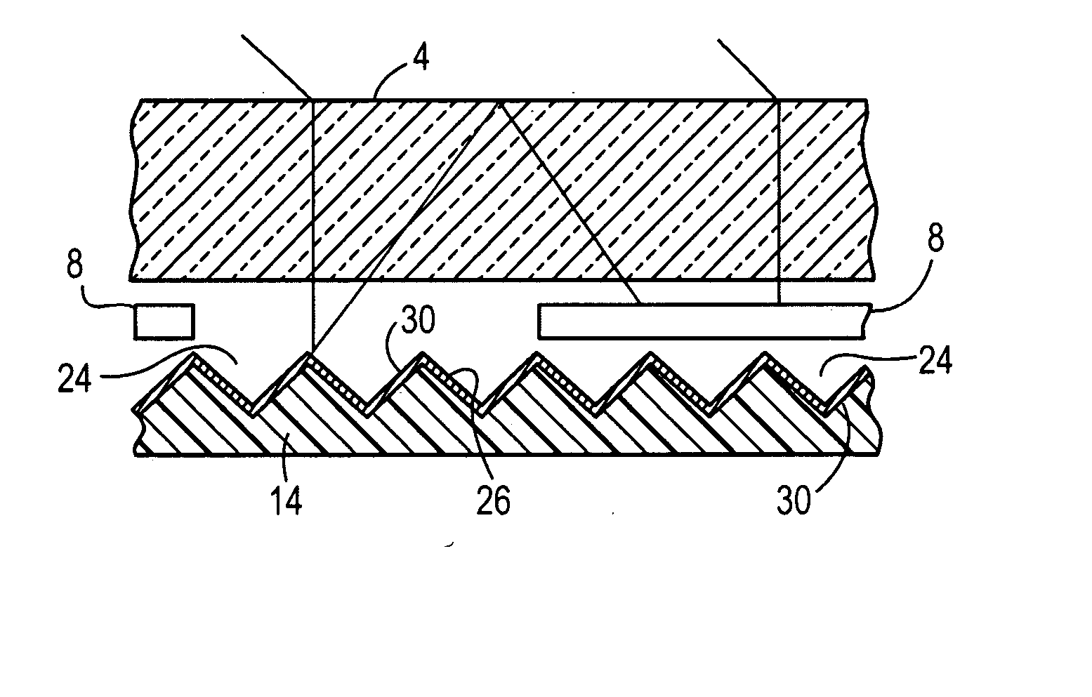
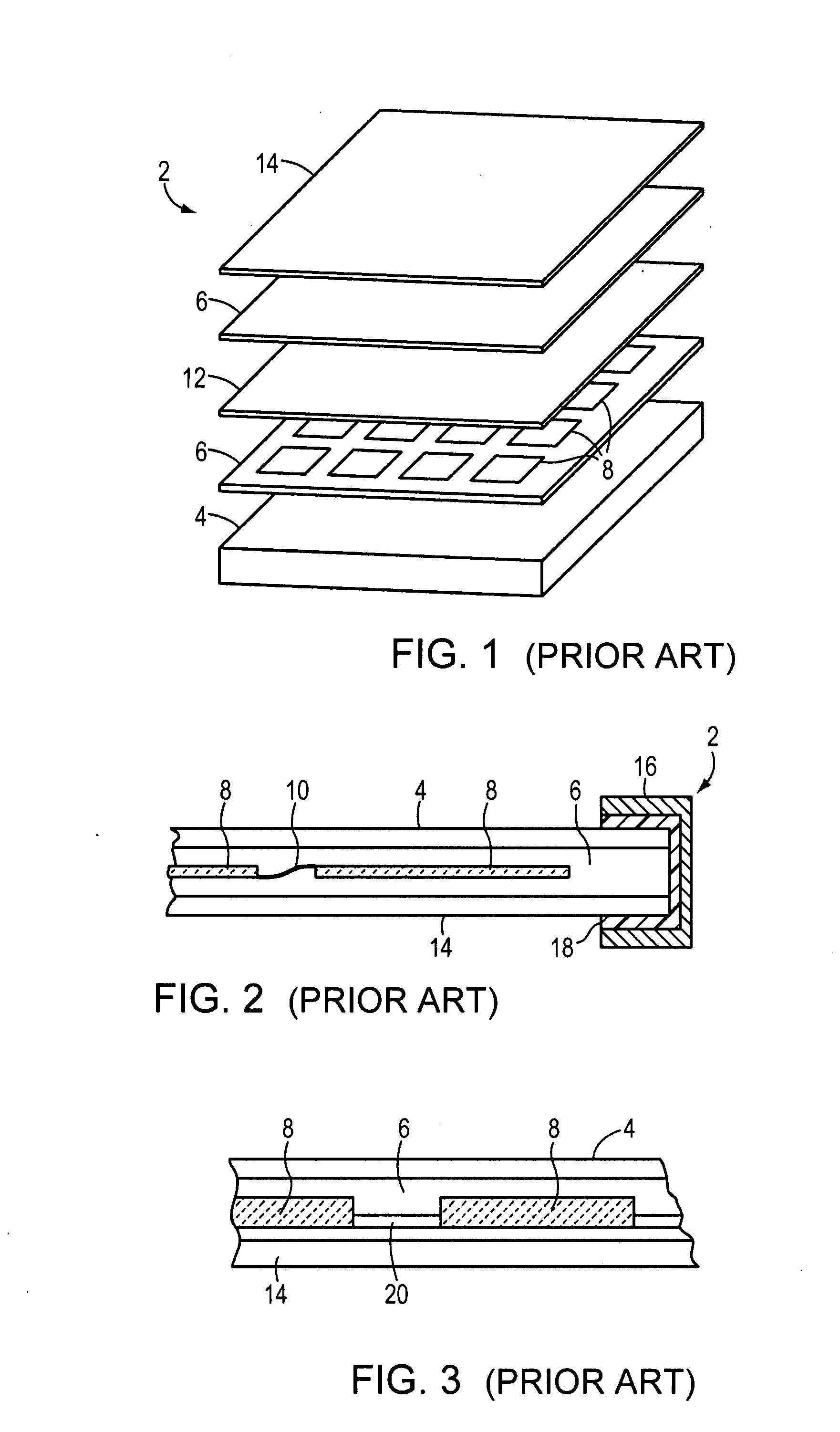
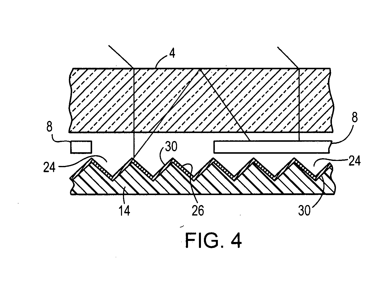
[0042]FIGS. 1 and 2 schematically illustrate components of a conventional form of laminated solar cell module 2 that may be modified to incorporate the present invention. The components used to construct the solar cell module comprise a stiff and transparent front cover or superstrate 4 that is made of glass or a suitable plastic such as polycarbonate or an acrylic polymer, a first layer 6 of a light transmitting encapsulant such as EVA, an array of separately formed crystalline silicon solar cells 8 interconnected by conductors 10 (FIG. 2), a porous scrim sheet 12 (omitted from FIG. 2 for convenience of illustration), a second layer 6 of a transparent encapsulant, and a protective back cover or backskin 14 made of an electrically insulating material, e.g. Tedlar™. The conductors 10 commonly are arranged with a stress-relief loop.

[0043] Each PV cell has a p-n junction (not shown) adjacent to its front radiation-r...


PUM

PropertyMeasurementUnit
angleaaaaaaaaaa
pressureaaaaaaaaaa
angleaaaaaaaaaa

Abstract

A photovoltaic module comprises electrically interconnected and mutually spaced photovoltaic cells that are encapsulated by a light-transmitting encapsulant between a light-transparent front cover and a back cover, with the back cover sheet being an ionomer / nylon alloy embossed with V-shaped grooves running in at least two directions and coated with a light reflecting medium so as to provide light-reflecting facets that are aligned with the spaces between adjacent cells and oriented so as to reflect light falling in those spaces back toward said transparent front cover for further internal reflection onto the solar cells, whereby substantially all of the reflected light will be internally reflected from said cover sheet back to the photovoltaic cells, thereby increasing the current output of the module. The internal reflector improves power output by as much as 67%.

Description

RELATED APPLICATION [0001] This application is a continuation of U.S. application Ser. No. 10 / 458,616, filed Jun. 10, 2003, entitled “Photovoltaic Module With Light Reflecting Backskin.” The entire teachings of the above application are incorporated herein by reference.GOVERNMENT SUPPORT [0002] The invention was supported, in whole or in part, by a grant Subcontract No. ZAX-8-17647-10 from the Department of Energy. The Government has certain rights in the invention.FIELD OF THE INVENTION [0003] This invention relates to solar cell modules having reflector means for utilizing light impinging on areas between solar cells which would normally not be utilized in photoelectric conversion, whereby to increase the power output of the module. BACKGROUND OF THE INVENTION [0004] Photovoltaic (PV) cells used for photoelectric conversion, e.g., silicon solar cells, are relatively small in size, typically measuring 2-4″ on a side in the case of cells made from rectangular EFG-grown substrates. I...

Claims


Application Information

Patent Timeline
Patent Type & Authority Applications(United States)
IPC IPC(8): H01L31/048
CPCB32B17/10018B32B17/10678B32B17/10743H01L31/056H01L31/18Y02E10/52H01L31/048H01L31/0547
Inventor GONSIORAWSKI, RONALD C.GONSIORAWSKI, STEVEN
Owner GONSIORAWSKI RONALD C
Why Eureka
Try Eureka