Elongated cross coil assembly for use in borehole location determination

a cross-coil assembly and location determination technology, applied in the direction of directional drilling, survey, borehole/well accessories, etc., can solve the problems of difficult measurement or setting of rotational orientation, add to the complexity and cost of the drill guidance system, and exist with other current methods

Active Publication Date: 2008-01-03
HALLIBURTON ENERGY SERVICES INC
View PDF11 Cites 40 Cited by
  • Summary
  • Abstract
  • Description
  • Claims
  • Application Information

AI Technical Summary

Benefits of technology

[0007]The present invention overcomes the difficulties encountered in the use of prior drill guidance systems by providing an improved method and apparatus for tracking and drilling boreholes along predetermined paths, typically, but not only, when the borehole is to be accurately placed with respect to the path of another existing borehole. The method and apparatus of the invention include the use of an elongated pair of crossed coils that are deployed, for example, in the existing borehole. Both coils are energized with alternating current in such a way as to produce a rotating magnetic moment that generates a rotating, elliptically polarized magnetic field at the observation point in the borehole being drilled or surveyed. Measurements of this magnetic field are made at the observation point, in accordance with the p

Problems solved by technology

However, problems exist with these and other current methods.
Measuring or setting this rotational orientation is often difficult, in practice, and this adds to the complexity and cost of the drill guidance system.
A problem with this approach is that it does not wor

Method used


Image

  • Elongated cross coil assembly for use in borehole location determination
  • Elongated cross coil assembly for use in borehole location determination
  • Elongated cross coil assembly for use in borehole location determination

Examples


Embodiment Construction

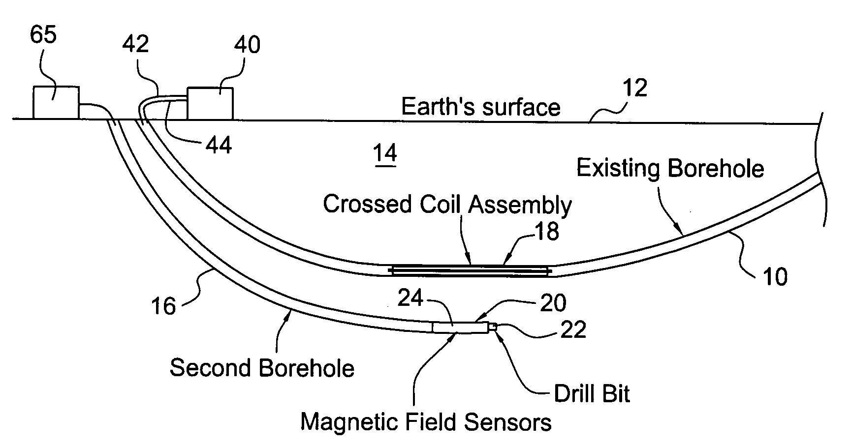
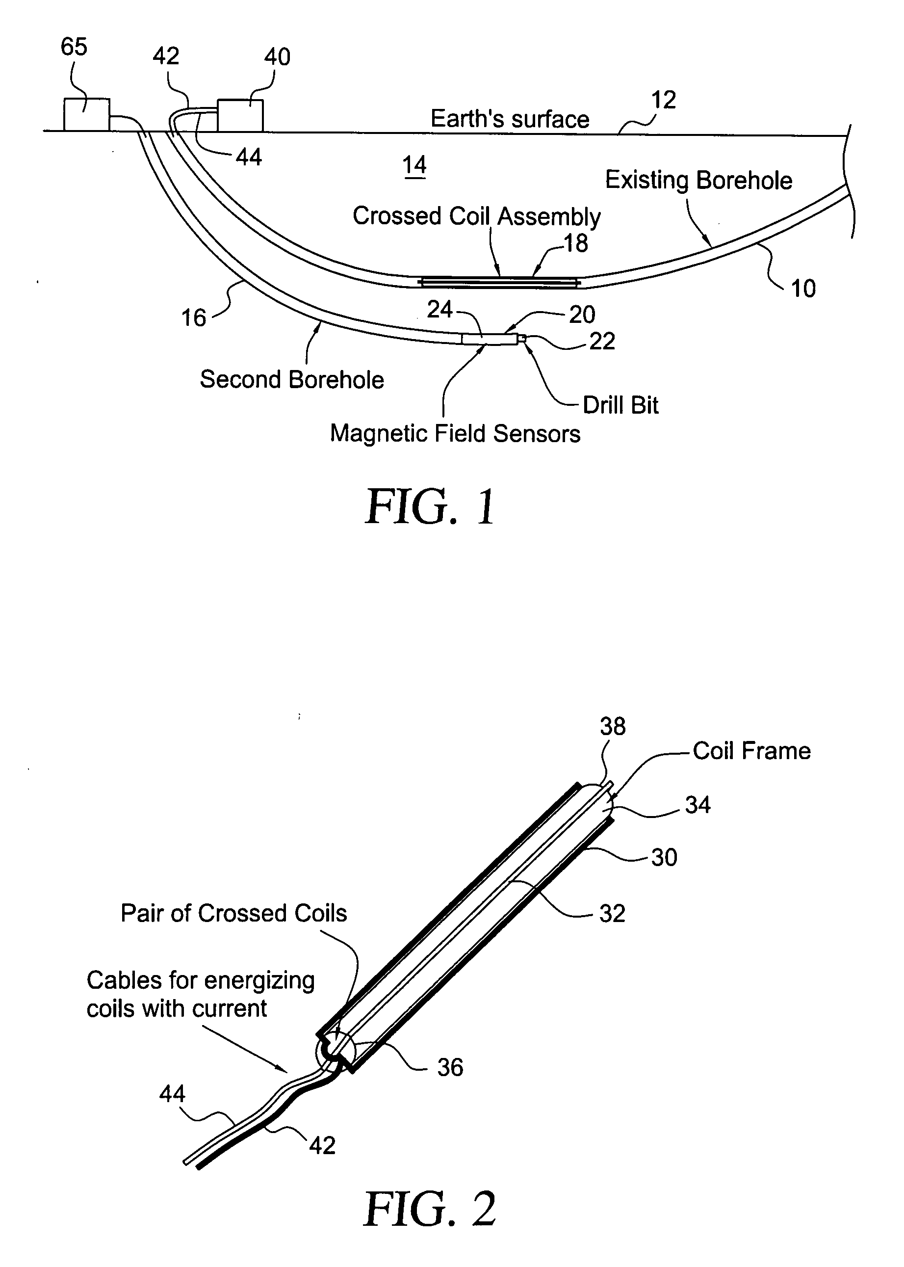
[0024]Turning now to a more detailed description of a preferred embodiment of the present invention, FIG. 1 illustrates a method and apparatus for measuring the relative locations of a borehole that is being drilled and an elongated magnetic field source. As illustrated, the field source may be located in an existing first borehole 10 that is located beneath the surface 12 of the earth 14 and a second borehole 16 is to be drilled along side the existing borehole. A crossed coil assembly, generally indicated at 18, is deployed in the existing borehole to provide a magnetic field for guiding the drilling of borehole 16, and a drilling tool 20, incorporating a drill bit 22 and conventional drilling control equipment, as well as suitable magnetic field sensors 24 for detecting the magnetic field produced by the crossed coil assembly, is located in borehole 16. The coil assembly 18 is positioned in the borehole 10 either with cables pulling it from either end of the existing borehole or ...


PUM


Abstract

An apparatus and method for measuring the location of one borehole relative to another includes a pair of elongated crossed coils deployed in the first borehole and an instrument containing magnetic field sensors deployed in the second borehole. The crossed coils are energized in quadrature by AC currents producing a rotating, elliptically polarized magnetic field at the second borehole. Mathematical analysis of the magnetic field sensor readings determines the location of the second borehole relative to the first. Both the distance and the rotational direction to the second borehole are determined as a function of depth of the sensors relative to that of the pair of crossed coils. No knowledge or measurement of the rotational orientation of the crossed coil in the first borehole is needed. Any twisting of the long coil in the borehole can be evaluated by noting the relative phase of the received elliptically polarized field as the depth of measurement is varied, and the relative distance between the boreholes and the corrections needed due to such twisting are determined.

Description

BACKGROUND[0001]This application claims the benefit of U.S. Provisional Application No. 60 / 817,248, entitled “Long Coil Pair for Tracking the Drilling of a Borehole”, filed Jun. 30, 2006, the disclosure of which is hereby incorporated herein by reference.[0002]The present invention relates, in general, to a method and apparatus for measuring the relative locations of boreholes and for drilling boreholes that are accurately placed relative to each other. More particularly, the invention relates to a drilling guidance tool that is deployed in an existing reference borehole, the tool incorporating a coil assembly having an elongated core carrying a pair of elongated crossed coils that are energized with alternating current so as to produce a rotating, elliptically polarized magnetic field. An instrument containing magnetic field sensors is deployed in a second borehole that is being drilled to measure the rotating magnetic field and to track and to guide the drilling.[0003]The technolo...

Claims


Application Information

Patent Timeline
IPC IPC(8): E21B7/00E21B44/00
CPCE21B47/02216E21B47/0228
Inventor KUCKES, ARTHUR F.SUSMANN, HERBERT J.
Owner HALLIBURTON ENERGY SERVICES INC
Why Eureka
Try Eureka