
Low power LCD source driver

a low-power, source driver technology, applied in the direction of electric digital data processing, instruments, computing, etc., can solve the problems of reducing the acceptance of mobile devices, affecting the operation of mobile devices, so as to reduce the power consumption of source drivers ics and reduce the parasitic capacitance

Inactive Publication Date: 2008-01-03
HIMAX TECH LTD
View PDF6 Cites 24 Cited by
  • Summary
  • Abstract
  • Description
  • Claims
  • Application Information

AI Technical Summary

Benefits of technology

The present invention provides a solution to reduce the power consumption of source driver ICs by dividing data buses into several segments controlled by a bus buffer. This reduces parasitic capacitance and allows for a more efficient transmission of image data. The invention also includes a source driver circuit with a plurality of shift registers, a line buffer, a D / A converter, and a buffer using the D / A converter as a reference. The line buffer contains at least one bus buffer for receiving and dispatching image data buses to channel units. The technical effects of the invention include improved data transmission efficiency and reduced power consumption.

Problems solved by technology

Without long battery life, acceptance of mobile devices would decrease and the convenience of mobile devices would be diminished.
Hence, the power consumption of source driver ICs constitutes a problem as liquid crystal display panels continue to become higher resolution and are embedded into mobile devices.
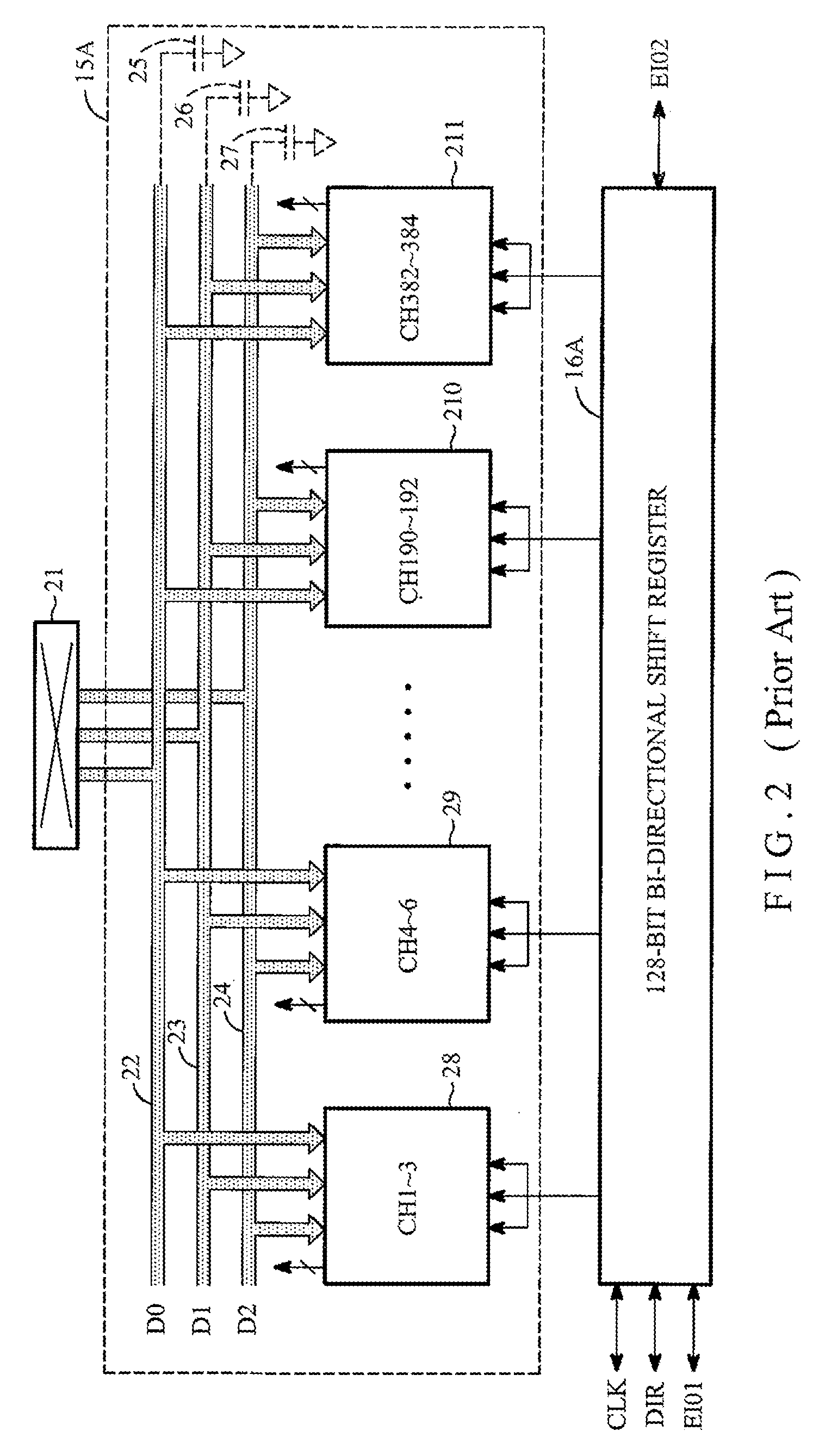
The data buses inside the source driver ICs consume most of power.
Although this disclosure reduces the power consumption of the source driver ICs by utilizing at least one voltage adder to eliminate one D / A converter, it does not describe how to reduce the power consumption generated on the data bus of the digital video signals.
As discussed above, the source driver ICs are burdened with most of the power consumption for displaying images on liquid crystal display panels due to line sequential driving systems that are utilized in most of modern LCD flat panels.
The busy data transmission on the video data bus consumes a large portion of power.

Method used


Image

  • Low power LCD source driver
  • Low power LCD source driver
  • Low power LCD source driver

Examples


Embodiment Construction

[0026]Apparatuses for driving a display device are disclosed. It will be clear, however, that the present invention may be practiced without some or all of these specific details. In other instances, well known process operations have not been described in detail in order not to unnecessarily obscure the present invention.

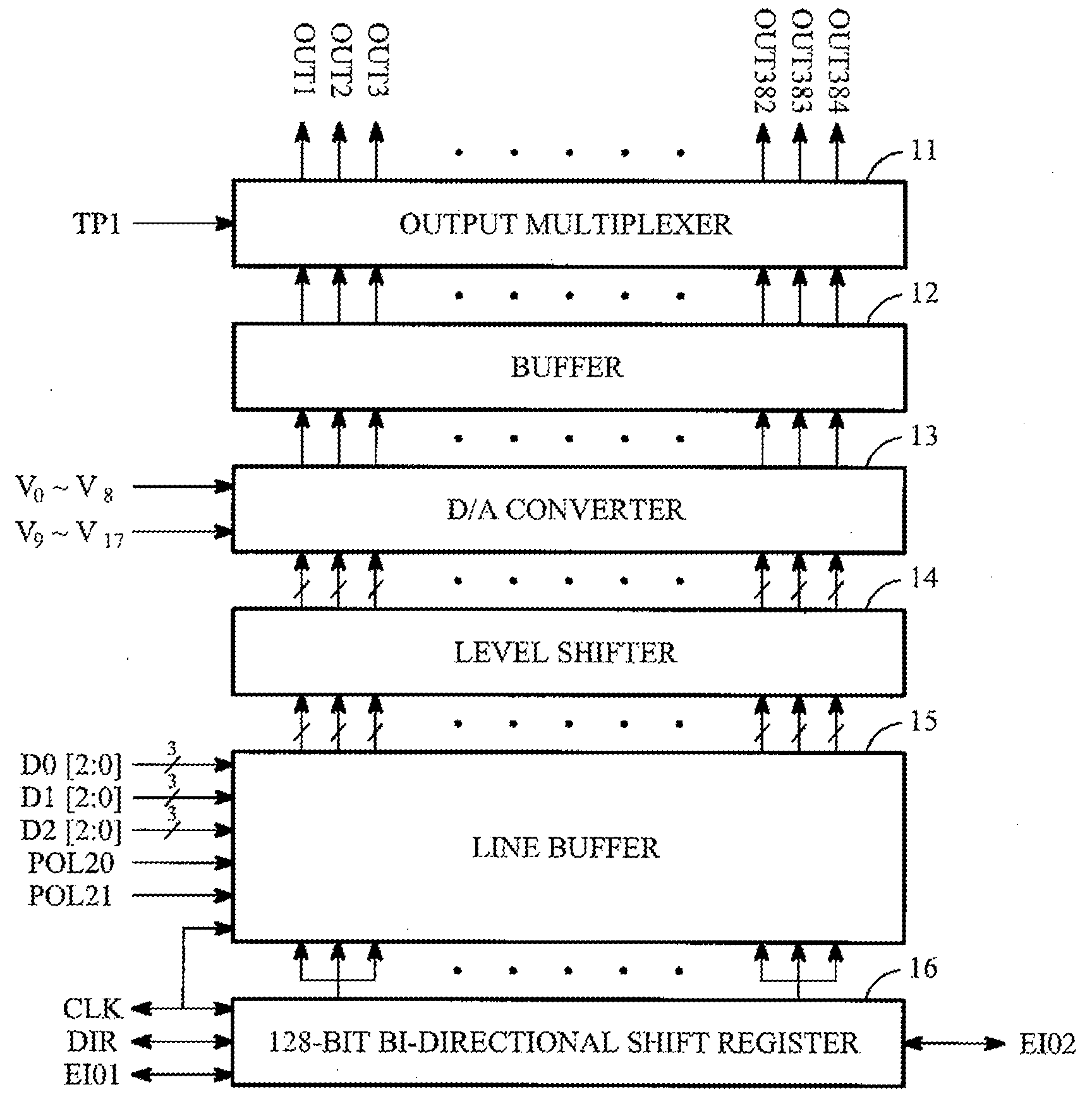
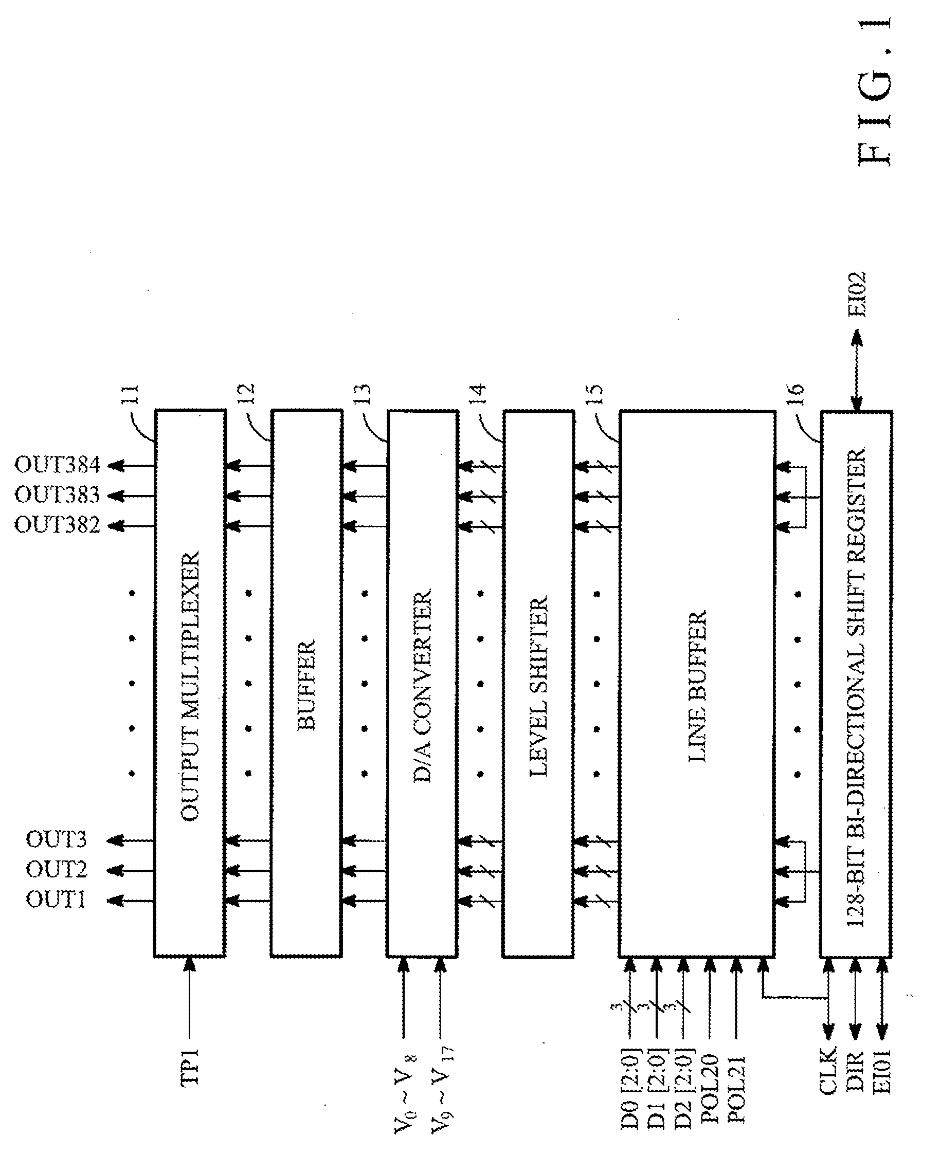
[0027]In FIG. 1, the architecture of a source driver IC is shown, in accordance with one embodiment. The source driver can have 384 channels and can include a 128-bit bi-directional shift register 16, a line buffer circuit 15, a level shifter circuit 14, a D / A converter circuit 13, a buffer circuit 12 and an output multiplexer circuit 11. In order to receive image data from the other circuit components, a clock signal CLK can be sent to the 128-bit bi-directional shift register 16 of the source driver. When the image data contains color information, more complicated signals like D0[2:0], D1[2:0] and D2[2:0] can be input into the line buffer circuit 15 of the source...


PUM


Abstract

The invention provides solutions to solve the power consumption of the image data buses of an LCD source driver. With a bus buffer provided in one embodiment of the invention, a first image data buses are divided into several groups. Each group of image data buses is dispatched by the bus buffer. It is possible in one embodiment of the invention that some groups are active when the others are passive. Therefore, unnecessary power consumption is cut off. Despite the power saved by the management of the bus buffer, the parasitic capacitance of each group of image data buses is much smaller than that of the image data buses in the prior art. Moreover, the management of the bus buffer can depend upon the layout patterns or the layout locations of circuit components so that the driving strength of the bus buffer may be modified according to the layout pattern or the layout locations.

Description

APPLICATION FOR CLAIM OF PRIORITY[0001]This application claims priority as a Continuation-In-Part under 35 U.S.C. §120 to U.S. patent application Ser. No. 11 / 428,141, filed Jun. 30, 2006 and entitled “Data Bus Power Down for Low Power LCD Source Driver.” The disclosure of the above identified application is incorporated herein by reference.BACKGROUND[0002]I. Field of the Invention[0003]The present invention generally relates to drive circuits for display devices such as liquid crystal display devices, and more particularly, certain embodiments of the invention relate to drive circuit devices that reduce power consumption.[0004]II. Background of the Invention[0005]As liquid crystal display devices continue to replace traditional CRT displays at an aggressive pace the improvements in drive circuit devices have also accelerated. A liquid crystal display (LCD) device can be an active-matrix type, which has a plurality of active elements arranged on a flat substrate, e.g., flat glass, in...

Claims


Application Information

Patent Timeline
Patent Type & Authority Applications(United States)
IPC IPC(8): G09G5/00
CPCG09G3/3611G09G2370/08G09G2310/027G09G3/3688
Inventor CHANG, YU-JUI
Owner HIMAX TECH LTD
Learn More