Method for anchoring a mitral valve

a technology of mitral valve and anchoring device, which is applied in the field of minimally invasive cardiac surgery, can solve the problems of difficult mitral valve case and inability to perform percutaneous surgery, and achieve the effect of avoiding resection and reducing the risk of resection

Active Publication Date: 2008-01-03
KARDIUM
View PDF98 Cites 441 Cited by
  • Summary
  • Abstract
  • Description
  • Claims
  • Application Information

AI Technical Summary

Problems solved by technology

The mitral valve is a particularly difficult case as the heart has an unfavorable geometry for anchoring a replacement valve.
This procedure is not practical for percutaneous surgery.

Method used


Image

  • Method for anchoring a mitral valve
  • Method for anchoring a mitral valve
  • Method for anchoring a mitral valve

Examples


Embodiment Construction

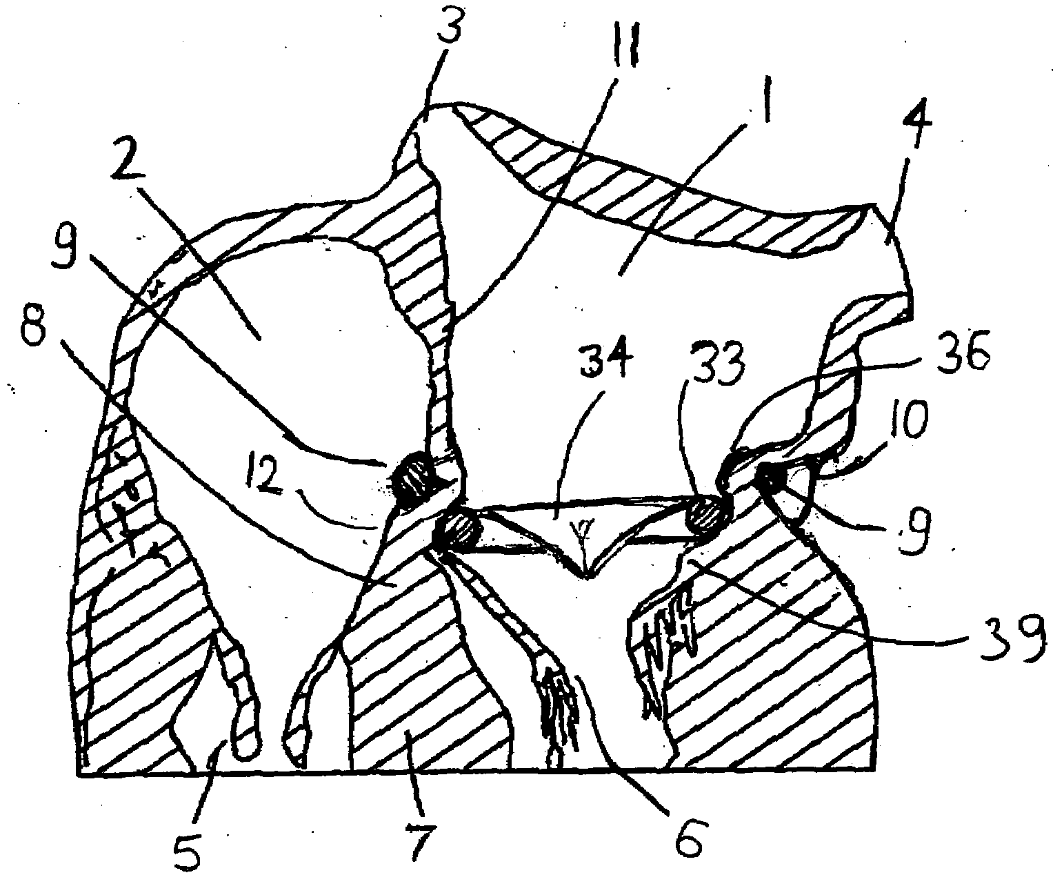
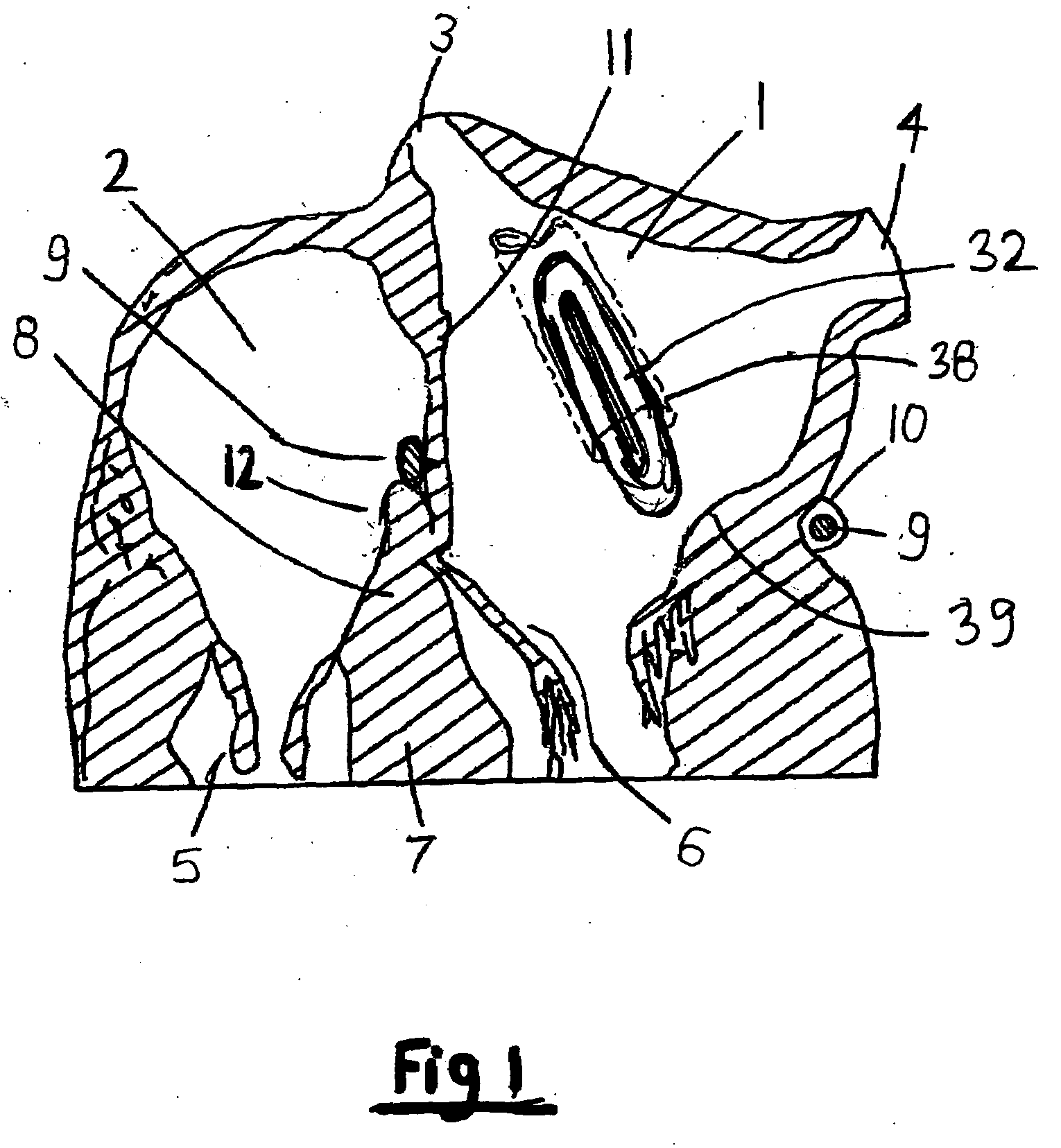
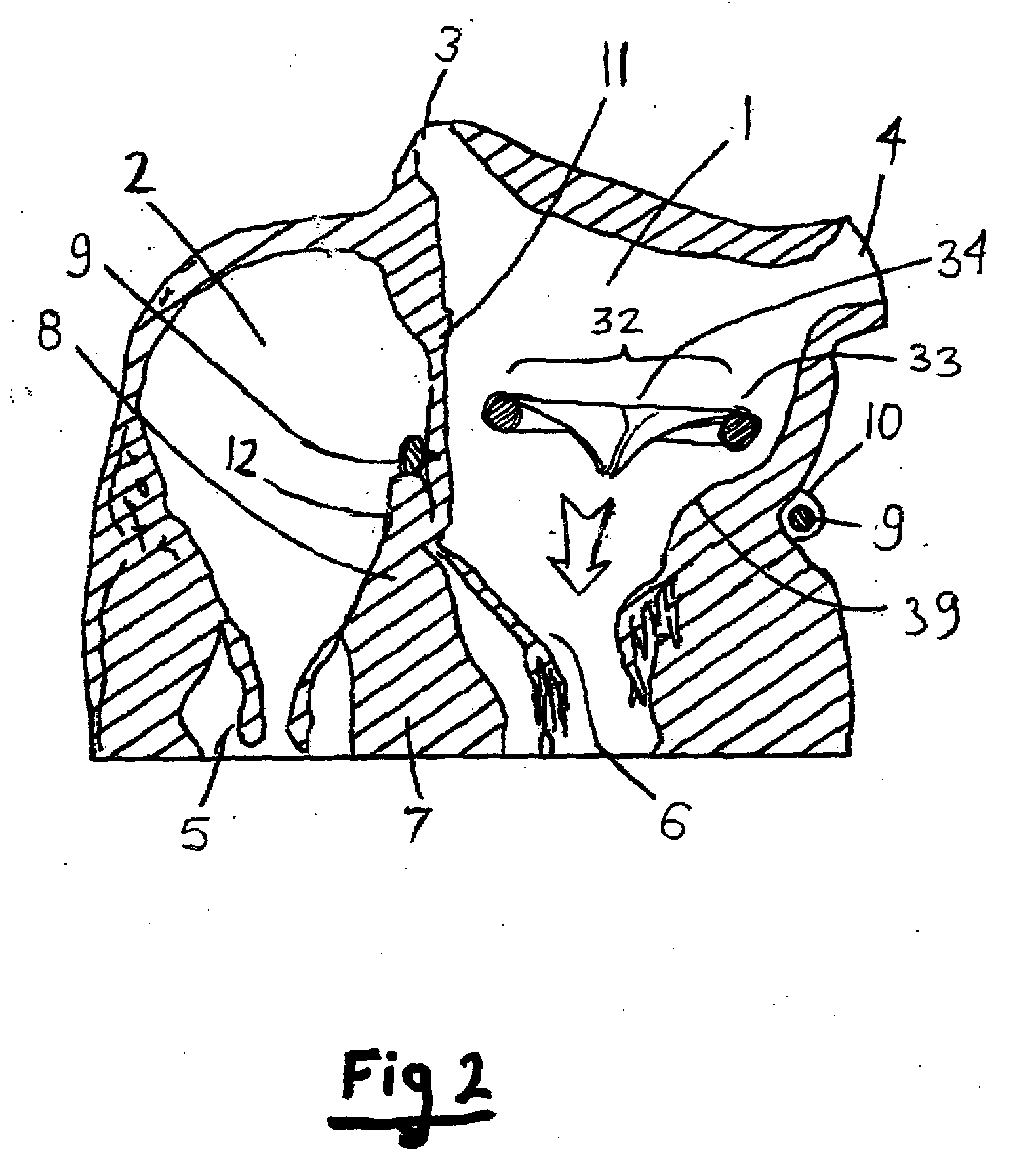
[0013]Referring now to FIG. 1, the cross section of the upper part of the heart shows the left atrium 1, the right atrium 2, pulmonary veins 3 and 4, tricuspid valve 5 and mitral valve 6, interventricular septum 7, atrioventricular septum 8, coronary sinus 10, interartial septum 11, and tendon of Todaro12. An artificial mitral valve 32 is introduced into the left atrium to replace a defective mitral valve 6. The artificial valve is of flexible construction in order to be deployed percutaneously via a catheter 38. For deployment it is compressed into an elongated oval shape. The art of percutaneous deployment is well known in minimally invasive surgery. One way to deploy valve 32 is to pass catheter 38 via septum 11, after entering the right atrium via the superior vena cava. The anchoring tool 9 is shown in FIG. 1 already inside the coronary sinus 10. The periphery of mitral valves 6 is less flexible and forms a shape 39 known as the mitral valve annulus.

[0014]Referring now to FIG. ...


PUM


Abstract

An artificial mitral valve is anchored in the left atrium by placing the valve between the annulus of the natural mitral valve and an artificial annulus. The artificial annulus is formed by inserting a tool into the coronary sinus, and adjusting the tool to force the wall of the left atrium to form an annulus above the artificial valve, this locking it in place and forming a hemostatic seal.

Description

FIELD OF THE INVENTION [0001]The invention relates to minimally invasive cardiac surgery.BACKGROUND OF THE INVENTION [0002]The art of artificial heart valves is well known. Recently there is a strong interest in minimally invasive methods of replacing defective heart valves, an in particular in percutaneous deployment methods. In those procedure, the new valve and all the steps to install it, are delivered via a fairly narrow catheter, typically 8-10 mm diameter.[0003]Replacing major surgery with the small incision needed for inserting such a catheter is a major step in cardiac surgery.[0004]The mitral valve is a particularly difficult case as the heart has an unfavorable geometry for anchoring a replacement valve. In conventional cardiac surgery the new valve is sutured to the tissue around the natural valve, which is surrounded by an annular ring of more rigid tissue known as the valve annulus. This procedure is not practical for percutaneous surgery. The main object of the invent...

Claims


Application Information

Patent Timeline
Patent Type & Authority Applications(United States)
IPC IPC(8): A61F2/24
CPCA61F2/2412A61F2/2433A61F2/2451A61F2/2418A61F2210/009A61F2/2442A61F2/2466A61F2250/006
Inventor LICHTENSTEIN, SAMUEL VICTORGELBARX, DANIEL
Owner KARDIUM
Why Eureka
Try Eureka