Exhaust gas purification system for internal combustion engine and method for exhaust gas purification

a technology internal combustion engine, which is applied in the direction of machines/engines, mechanical equipment, electric control, etc., can solve the problems of excessive abrupt increase in catalyst bed temperature, and disadvantages of exhaust gas purification system, so as to maintain fuel economy

Active Publication Date: 2008-01-10
TOYOTA JIDOSHA KK +1
View PDF3 Cites 21 Cited by
  • Summary
  • Abstract
  • Description
  • Claims
  • Application Information

AI Technical Summary

Benefits of technology

[0013] The present invention provides an exhaust gas purification system for an internal combustion engine and an exhaust gas purification method, which maintains fuel economy during the sulfur poisoning recovery control.
[0015] According to the first aspect, the sulfur poisoning recovery control is executed after the PM catalyst regeneration control for the purpose of “soot removal” in which the PM deposits in the catalyst are burned. For the sulfur poisoning recovery control, the target value for controlling the intake air volume during deceleration is preset smaller than for the PM catalyst regeneration control in order to reduce the intake air volume during deceleration. The catalyst bed temperature is thus prevented from dropping, and therefore maintained at a level appropriate to sulfur poisoning recovery. This results in more efficient catalyst recovery from sulfur poisoning, and therefore a shorter recovery time. Further, the catalyst bed temperature can be maintained at a high level, thereby reducing a quantity of supplemental fuel needed to raise the catalyst bed temperature.
[0016] According to the first aspect, when the amount of PM deposits is less than a reference amount when the PM catalyst regeneration control is executed, the target value for controlling the intake air volume during deceleration may be preset smaller than in the case where the amount of PM deposits is equal to or larger than the reference amount. Using such a configuration, the appropriate volume of intake air volume during deceleration to burn the PM deposits in the catalyst may be determined. This prevents a drop in catalyst bed temperature due to the excessive increase in intake air volume during the PM catalyst regeneration. Thereby, more efficient PM catalyst regeneration is achieved.
[0023] According to the aforementioned aspects of the invention, the sulfur poisoning recovery control is executed after the PM catalyst regeneration control. For the sulfur poisoning recovery control, the target value for controlling the intake air volume during deceleration is preset smaller than for the PM catalyst regeneration control, in order to reduce the intake air volume during deceleration. The catalyst bed temperature is thus prevented from dropping, and therefore maintained at a level appropriate to sulfur poisoning recovery. This results in more efficient catalyst recovery from sulfur poisoning, so that the fuel economy is maintained during the sulfur poisoning recovery control.

Problems solved by technology

The exhaust gas purification system also has a disadvantage.
This may cause an excessive increase in catalyst bed temperature.
This can cause an abrupt increase in the catalyst bed temperature.
As a result of such reduced catalyst bed temperatures, the recovery of the catalyst from sulfur poisoning is more difficult.
Accordingly, it takes longer for the NOx storage reduction catalyst to recover from sulfur poisoning, which increases the supplemental fuel supply quantity.

Method used


Image

  • Exhaust gas purification system for internal combustion engine and method for exhaust gas purification
  • Exhaust gas purification system for internal combustion engine and method for exhaust gas purification
  • Exhaust gas purification system for internal combustion engine and method for exhaust gas purification

Examples


Embodiment Construction

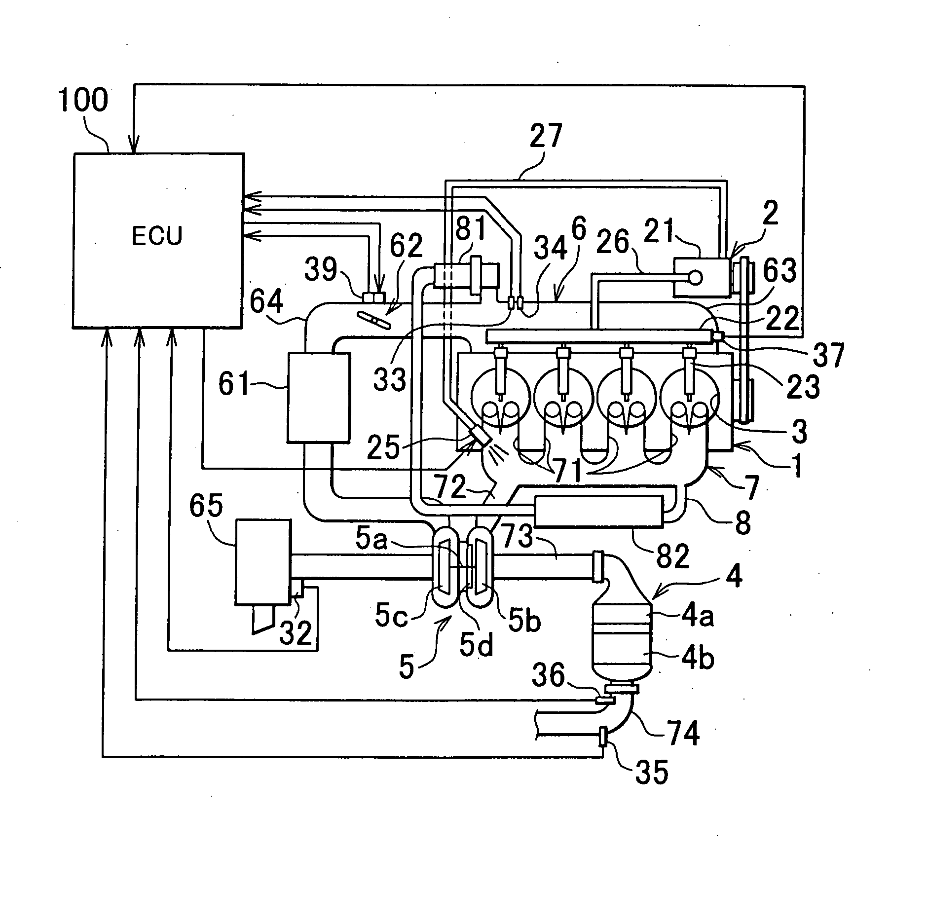
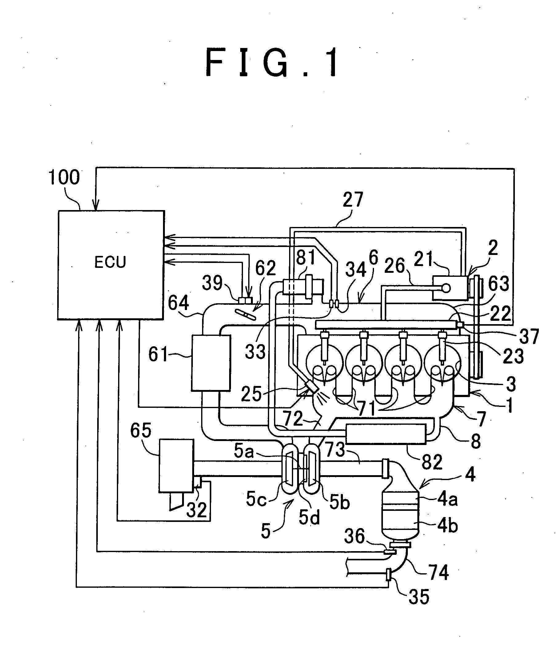
[0029] One embodiment of the invention will be described below with reference to the drawings. A general configuration of a diesel engine using a supplemental fuel supply apparatus of the invention is described with reference to FIG. 1.

[0030] In this embodiment, the diesel engine 1 (hereinafter referred to as “engine 1”) is a common rail direct-injection four-cylinder engine. The engine 1 includes, as main components, a fuel supply system 2, combustion chambers 3, an intake system 6 and an exhaust system 7.

[0031] The fuel supply system 2 includes a fuel supply pump 21, a common rail 22, injectors (fuel injection valves) 23, a supplemental fuel valve 25, an engine fuel passage 26 and a supplemental fuel passage 27.

[0032] The fuel supply pump 21 draws fuel from the fuel tank and pressurizes the fuel to supply the high-pressure fuel to the common rail 22 through the engine fuel passage 26. The common rail 22 functions as an accumulator to maintain the pressure of fuel supplied from ...


PUM


Abstract

A PM catalyst regeneration control for the purpose of “soot removal” is performed prior to a sulfur poisoning recovery control. In the PM catalyst regeneration control, PM deposits in a catalyst are burned. A target throttle opening degree for the sulfur poisoning recovery control is preset smaller than a target throttle opening for the PM catalyst regeneration control in order to reduce the intake air volume during deceleration. A catalyst bed temperature is thus prevented from dropping, and therefore maintained at a level appropriate to sulfur poisoning recovery. Controlling the intake air volume during deceleration in such a manner results in more efficient catalyst recovery from sulfur poisoning, so that the fuel economy is maintained during the sulfur poisoning recovery control.

Description

INCORPORATION BY REFERENCE [0001] The disclosure of Japanese Patent Application No. 2006-169345 filed on Jun. 19, 2006 including the specification, drawings and abstract is incorporated herein by reference in its entirety. BACKGROUND OF THE INVENTION [0002] 1. Field of the Invention [0003] The present invention relates to a system and a method for purifying exhaust gas from an internal combustion engine using a catalyst. More particularly, the invention relates to an exhaust gas purification system for an internal combustion engine that includes a supplemental fuel valve for supplying supplemental fuel to an exhaust passage, as well as relates to an exhaust gas purification method. [0004] 2. Description of the Related Art [0005] The exhaust gas purification system for purifying exhaust gas from the internal combustion engine, such as a diesel engine, (hereinafter sometimes called engine) has, as one example, an NOx storage reduction catalyst and a particulate filter for trapping par...

Claims


Application Information

Patent Timeline
Patent Type & Authority Applications(United States)
IPC IPC(8): F01N3/035F01N3/023
CPCF01N3/0253F01N13/0097F01N3/0814F01N3/0821F01N3/0842F01N3/0885F01N9/002F01N2560/025F01N2560/06F02B37/00F02D11/10F02D41/0002F02D41/028F02D41/029F02D41/10Y02T10/47F01N3/035Y02T10/40
Inventor TAHARA, JUNHONJO, FUMINORI
Owner TOYOTA JIDOSHA KK
Why Eureka
Try Eureka