Metal organic chemical vapor deposition equipment

a technology of metal organic chemical vapor deposition and equipment, which is applied in the direction of chemically reactive gases, coatings, crystal growth processes, etc., can solve the problems of uniform thickness of formed films and is not conventionally possible to improve film formation efficiency, so as to achieve the effect of improving film formation efficiency

Inactive Publication Date: 2008-01-10
SUMITOMO ELECTRIC IND LTD
View PDF3 Cites 409 Cited by
  • Summary
  • Abstract
  • Description
  • Claims
  • Application Information

AI Technical Summary

Benefits of technology

[0010]Accordingly, an object of the present invention is to provide MOCVD equipment capable of improving film formation efficiency while allowing a formed film to have a uniform film thickness.

Problems solved by technology

As a result, there arises a problem of nonuniform thickness of a formed film.
As such, it is not conventionally possible to improve film formation efficiency while allowing the formed film to have a uniform thickness.

Method used


Image

  • Metal organic chemical vapor deposition equipment
  • Metal organic chemical vapor deposition equipment
  • Metal organic chemical vapor deposition equipment

Examples


first embodiment

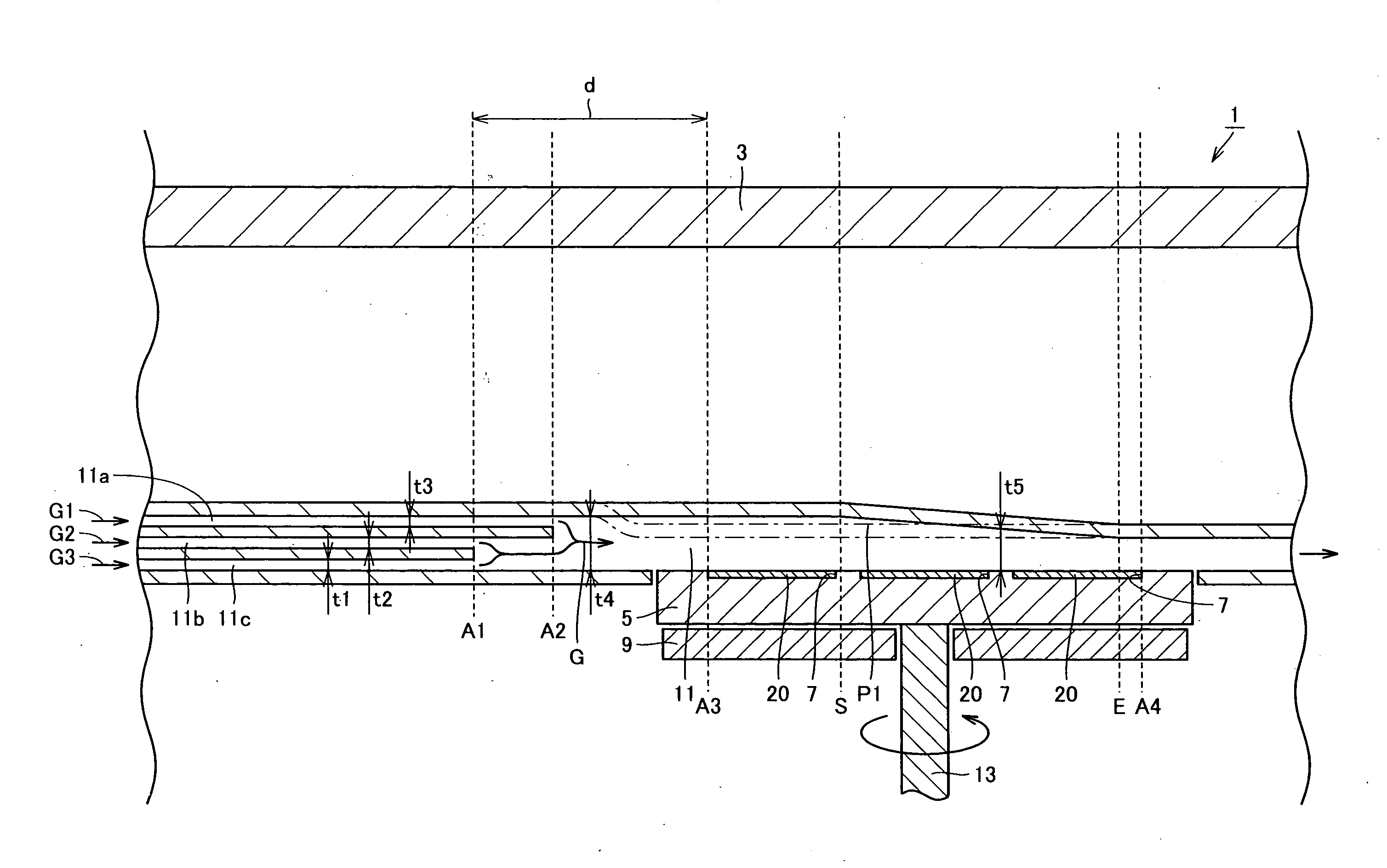
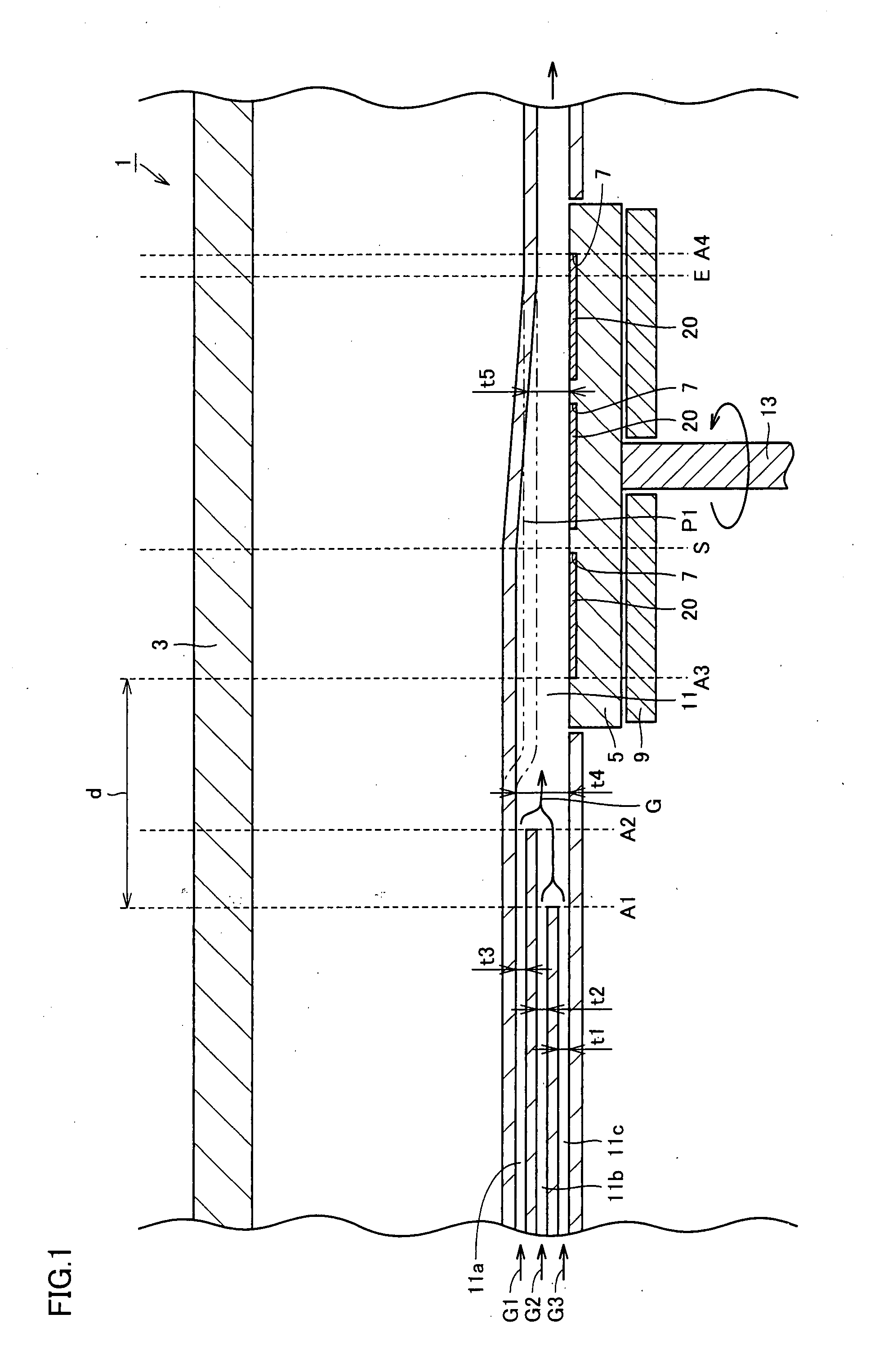
[0040]Referring to FIGS. 1 and 2, MOCVD equipment 1 according to the present embodiment includes a chamber 3, a susceptor 5 serving as a heating component, a heater 9, and a flow channel 11. Susceptor 5, heater 9, and flow channel 11 are placed in chamber 3. Flow channel 11 extends in a transverse direction in FIG. 1. A holding surface (a top surface in FIG. 1) of susceptor 5 faces an inner portion of flow channel 1.

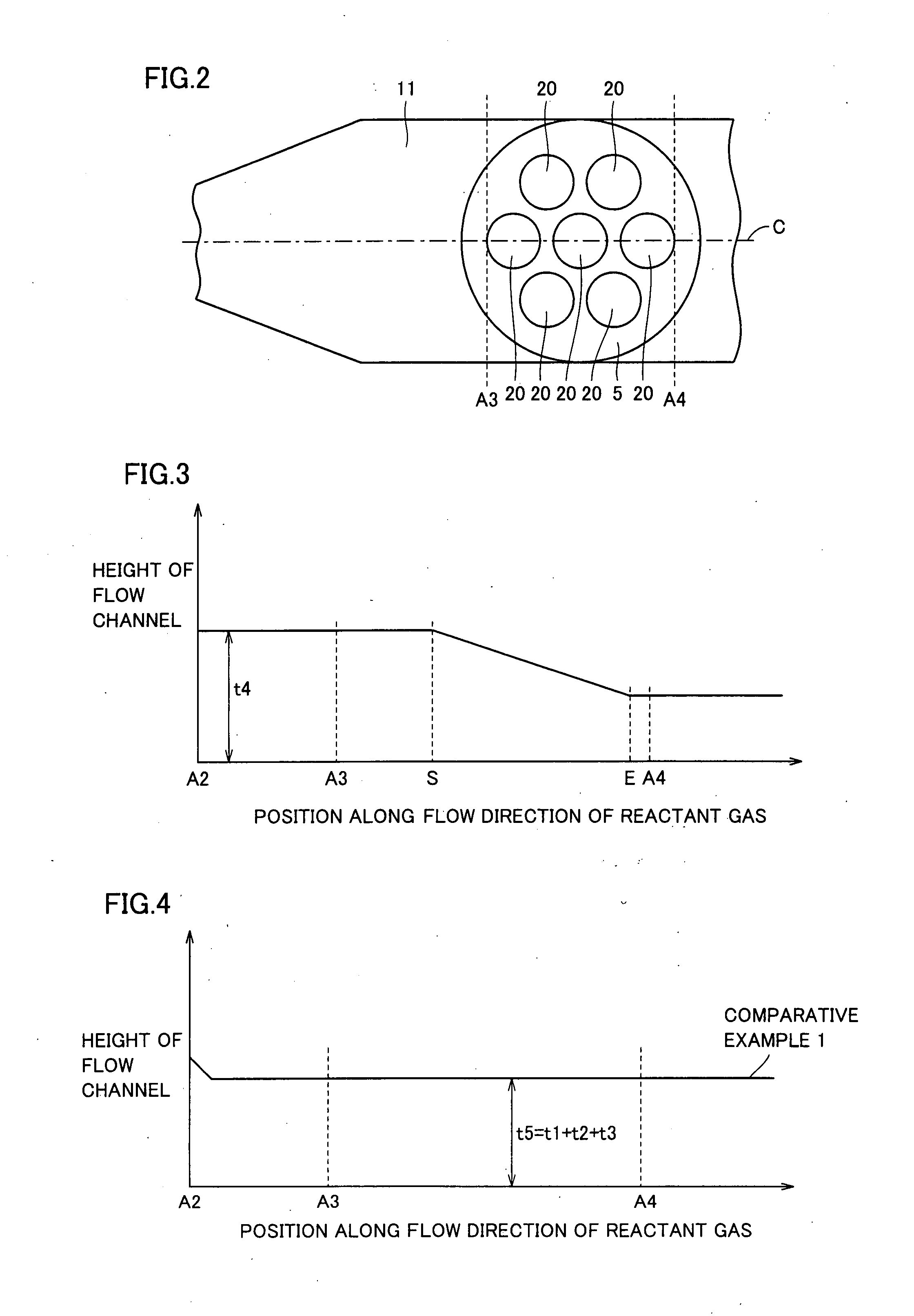
[0041]Susceptor 5, which has a disk shape, is placed on heater 9, which also has a disk shape. A rotary shaft 13 is attached to a lower part of susceptor 5, so that susceptor 5 is rotatable with the holding surface thereof kept facing the inner portion of flow channel 11. A plurality of concave portions 7, each having a circular shape in a plan view, are formed in the holding surface of susceptor 5. Substrates 20 are held in concave portions 7, respectively, and hence substrates 20 are heated. Referring to FIG. 2, in particular, seven concave portions 7 are formed in the...

second embodiment

[0059]Referring to FIGS. 8 and 9, in MOCVD equipment 1 according to the present embodiment, a height of flow channel 11 along the width direction thereof at the holding surface of susceptor 5 is monotonically decreased in a linear manner from each end portion (a height h1) to a central portion (a height h2) of the holding surface of susceptor 5. As shown in FIG. 10, the height of flow channel 11 along the width direction thereof at the holding surface of susceptor 5 may be monotonically decreased in a curved manner from each of the end portions (height h1) to the central portion (height h2) of the holding surface of susceptor 5. This causes an increase in reaction rate of the reactant gas at the central portion of the holding surface of susceptor 5, so that the reaction rate of flow channel 11 in the width direction thereof can be made uniformized.

third embodiment

[0060]Referring to FIG. 11, flow channel 11 according to the present embodiment has a bottleneck portion 30 near position A3. The height of flow channel 11 at bottleneck portion 30 is once decreased, kept constant at its local minimum value, and then increased. In FIG. 11, a top surface of flow channel 11 at bottleneck portion 30 has a convex shape. As shown in FIG. 12, however, a bottom surface of flow channel 11 at bottleneck portion 30 may have a concave shape.

[0061]With the MOCVD equipment according to the present embodiment, it is possible to increase a growth rate on the upstream side of position S and obtain the growth rate as approximately the same as the one at the downstream side of position S. As a result, it is possible to grow a uniform.

[0062]In other words, as also seen from Examples 1 and 2 of the present invention in FIG. 7, there is exhibited a three times or more difference in growth rate at the holding surface between the upstream side and the downstream side. Whe...


PUM

PropertyMeasurementUnit
distanceaaaaaaaaaa
distanceaaaaaaaaaa
reaction rateaaaaaaaaaa

Abstract

Metal organic chemical vapor deposition equipment is metal organic chemical vapor deposition equipment for forming a film on a substrate by using a reactant gas, and includes a susceptor heating the substrate and having a holding surface for holding the substrate, and a flow channel for introducing the reactant gas to the substrate. The susceptor is rotatable with the holding surface kept facing an inner portion of the flow channel, and a height of the flow channel along a flow direction of the reactant gas is kept constant from a position to a position, and is monotonically decreased from the position to the downstream side. It is thereby possible to improve film formation efficiency while allowing the formed film to have a uniform thickness.

Description

BACKGROUND OF THE INVENTION[0001]1. Field of the Invention[0002]The present invention relates to metal organic chemical vapor deposition equipment, and particularly relates to metal organic chemical vapor deposition equipment for forming a nitride semiconductor layer.[0003]2. Description of the Background Art[0004]A Metal Organic Chemical Vapor Deposition (MOCVD) method is one of the typical chemical vapor deposition methods, in which a Group III organic metal is vaporized and then thermally decomposed at a surface of a substrate, and reacted with a Group V gas to form a film. This method enables control of a film thickness and a composition, and is excellent in productivity, so that it is widely used as a film formation technique in manufacturing semiconductor equipment.[0005]MOCVD equipment used in the MOCVD method includes a chamber, a susceptor disposed in the chamber, and a conduit for allowing a reactant gas to flow at a surface of a substrate. In the MOCVD equipment, a film i...

Claims


Application Information

Patent Timeline
Patent Type & Authority Applications(United States)
IPC IPC(8): C23C16/458
CPCC23C16/303C23C16/45585C23C16/45504C30B35/00C30B25/165C23C16/4584C23C16/4586C30B25/12C30B25/10
Inventor UENO, MASAKIUEDA, TOSHIOTAKASUKA, EIRYO
Owner SUMITOMO ELECTRIC IND LTD
Why Eureka
Try Eureka