Variable valve actuation and engine braking

a technology of variable valves and valve actuation, which is applied in the direction of machines/engines, non-mechanical valves, valve arrangements, etc., can solve the problems of inability to provide a dedicated trigger valve for each engine valve, difficulty in adjusting the timing and/or amount of engine valve lift, and inability to meet the requirements of foregoing requirements

Inactive Publication Date: 2008-01-10
JACOBS VEHICLE SYST
View PDF11 Cites 46 Cited by
  • Summary
  • Abstract
  • Description
  • Claims
  • Application Information

AI Technical Summary

Benefits of technology

[0021] Applicant has developed an innovative valve actuation system for actuating at least two engine valves in an internal combustion engine, comprising: a first master piston and slave piston lost motion system adapted to actuate a first engine valve in a first engine cylinder; a second master piston and slave piston lost motion system adapted to actuate a second engine valve in the first engine cylinder; and a control valve in hydraulic communication with the first and second master piston and slave piston lost motion systems.

Problems solved by technology

In some cases, the use of fixed profile cams may make it difficult to adjust the timings and / or amounts of engine valve lift.
The foregoing requirements may present challenges to lost motion system designers due to the need to place the lost motion system into an already existing valve train in an engine compartment of limited size.
The combined size of the “valve” portion of the trigger valve and the solenoid may make it impractical to provide a dedicated trigger valve for each engine valve.
Typically, engine valves are required to open and close very quickly, and therefore the valve return springs are generally relatively stiff.
If left unchecked after a valve opening event, the valve return spring could cause the valve to impact its seat with sufficient force to cause damage to the valve and / or its seat.
When fluid is released from the lost motion system, the valve return spring may cause the engine valve to “free fall” and impact the valve seat at an unacceptably high velocity.
The engine valve may impact the valve seat with such force that it eventually erodes the valve or valve seat, or even cracks or breaks the valve.
In such instances, engine valve seating velocity has been limited by controlling the release of hydraulic fluid from the lost motion system instead of by a fixed cam profile.
The need to employ one or more valve seating devices thus adds complexity, cost, weight, and consumes limited engine compartment space.
Further, the need to employ valve seating devices increases risk of engine failure or damage should the device ever fail or be denied of hydraulic fluid.

Method used


Image

  • Variable valve actuation and engine braking
  • Variable valve actuation and engine braking
  • Variable valve actuation and engine braking

Examples


Embodiment Construction

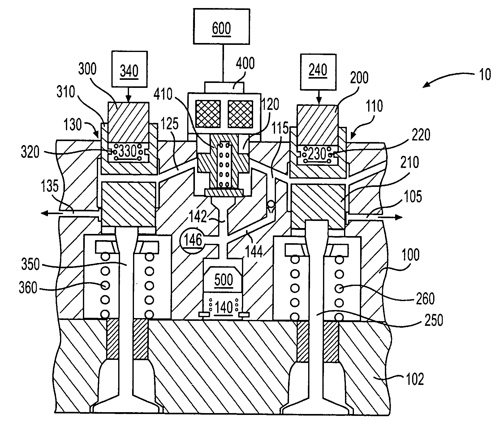
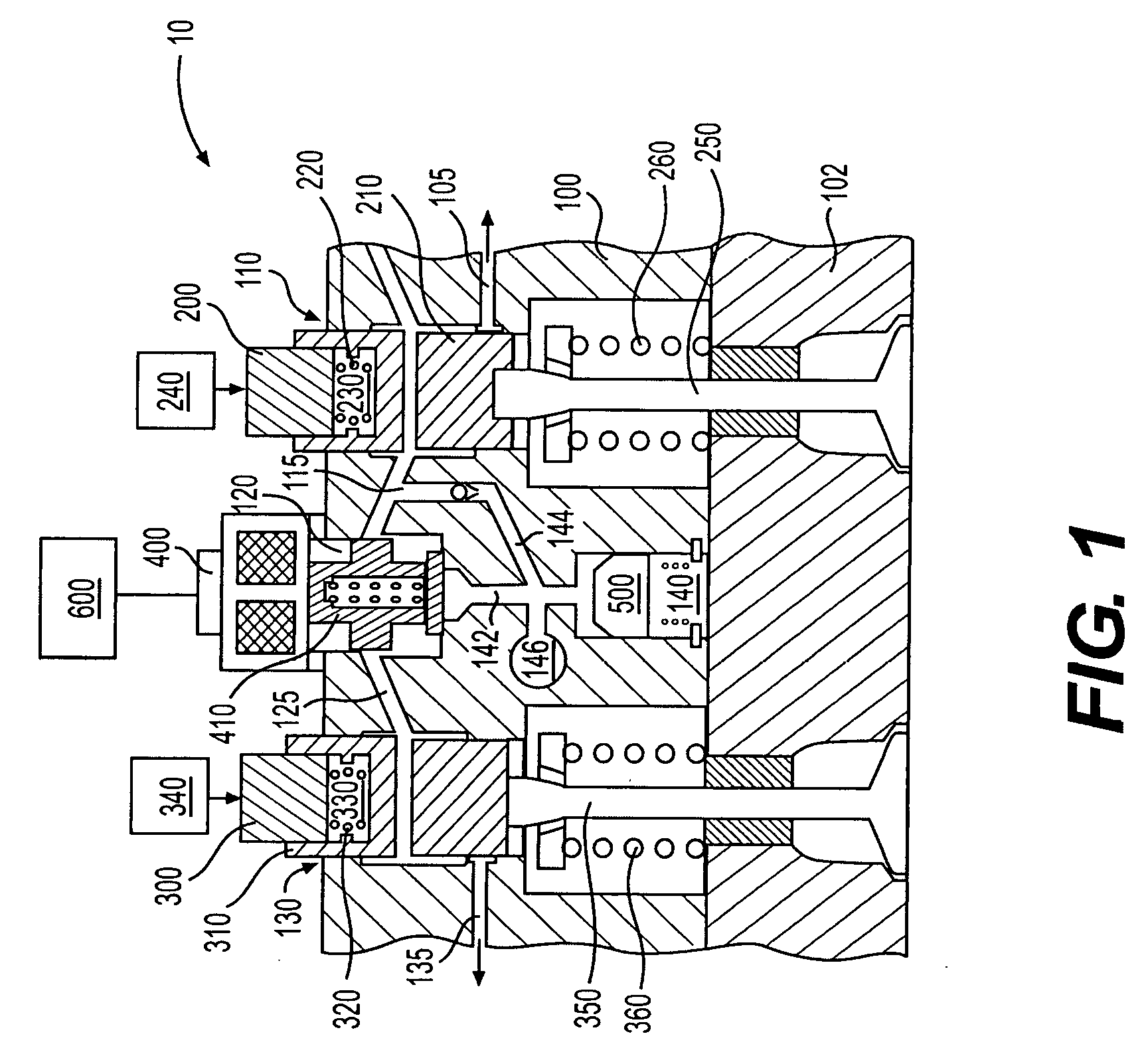
[0043] As embodied herein, the present invention includes both systems and methods of controlling the actuation of engine valves. Reference will now be made in detail to a first embodiment of the present invention, an example of which is illustrated in the accompanying drawings. A first embodiment of the present invention is shown in FIG. 1 as valve actuation system 10.

[0044] The valve actuation system 10 may include a housing 100 connected to an engine cylinder head 102. First and second engine exhaust valves 250 and 350 may be disposed in the cylinder head 102 to provide selective communication between an engine cylinder and an engine manifold (not shown). It is appreciated that the invention is not limited to use with exhaust valves, but may also be used with intake and / or auxiliary valves. The first and second engine valves 250 and 350 may be biased by valve springs 260 and 360, respectively, into closed positions.

[0045] The housing 100 may include a first tappet bore 110 and ...


PUM


Abstract

Systems and methods of actuating two engine valves associated with a common engine cylinder using one or more lost motion systems and one or more control valves are disclosed. The control valves are capable of selectively trapping hydraulic fluid in the lost motion systems for auxiliary engine valve actuations and selectively releasing the hydraulic fluid to default to cam controlled valve seating of the engine valves. The systems may provide a combination of main exhaust, compression release, exhaust gas recirculation and early exhaust valve opening in preferred embodiments.

Description

CROSS REFERENCE TO RELATED APPLICATIONS [0001] The present application is related to, and entitled to the benefit of the filing date of U.S. provisional patent application Ser. No. 60 / 817,108 filed Jun. 29, 2006, entitled Individual Valve Control For Variable Valve Timing or Braking, and the filing date of U.S. provisional patent application Ser. No. 60 / 817,204 filed Jun. 29, 2006, entitled Variable Valve Timing and Braking Through Guided Bridge, both of which are hereby incorporated by reference.FIELD OF THE INVENTION [0002] The present invention relates generally to systems and methods for controlling engine combustion chamber valves in an internal combustion engine. In particular, the present invention relates to systems and methods for providing lost motion engine valve actuation of one or more engine valves, preferably, but not necessarily, including lost motion engine braking. BACKGROUND OF THE INVENTION [0003] Engine combustion chamber valves, such as intake and exhaust valve...

Claims


Application Information

Patent Timeline
Patent Type & Authority Applications(United States)
IPC IPC(8): F01L9/02F01L9/12F01L9/10F01L9/14
CPCF01L1/267F01L9/02F01L2001/34446F01L9/025F01L13/06F01L9/023F01L9/12F01L9/14F01L9/10F01L13/04F02D13/02
Inventor NOSS, RYANRUGGIERO, BRIAN L.
Owner JACOBS VEHICLE SYST
Why Eureka
Try Eureka