Determination of battery predictive power limits

a technology of predictive power limits and battery systems, applied in the field of battery systems, can solve the problems of introducing other issues, and limiting the performance of vehicles,

Active Publication Date: 2008-01-10
CHEVRON TECH VENTURES
View PDF7 Cites 31 Cited by
  • Summary
  • Abstract
  • Description
  • Claims
  • Application Information

AI Technical Summary

Benefits of technology

[0007]A battery control module for use with a battery includes a voltage measuring module that measures battery voltage and a current measuring module that measures battery current. A power limit module communicates with the current and voltage measuring modules and once every time period estimates a battery current limit that corresponds with a future time period. The battery current limit is based on a predetermined voltage limit of the battery and a battery current and a battery voltage that correspond with a time period that precedes the future time period.

Problems solved by technology

In some applications, such as HEVs, these limits on battery power can periodically limit the performance of the vehicle.
Such a method introduces other issues, however.
In such a situation the vehicle performance will still be limited for a brief period while the HEV control system starts the engine.
However an idling engine wastes fuel and therefore does not provide an ideal solution.

Method used


Image

  • Determination of battery predictive power limits
  • Determination of battery predictive power limits
  • Determination of battery predictive power limits

Examples


Embodiment Construction

[0021]The following description of the preferred embodiment(s) is merely exemplary in nature and is in no way intended to limit the invention, its application, or uses. For purposes of clarity, the same reference numbers will be used in the drawings to identify the same elements. As used herein, the term module or device refers to an application specific integrated circuit (ASIC), an electronic circuit, a processor (shared, dedicated, or group) and memory that execute one or more software or firmware programs, a combinational logic circuit, and / or other suitable components that provide the described functionality.

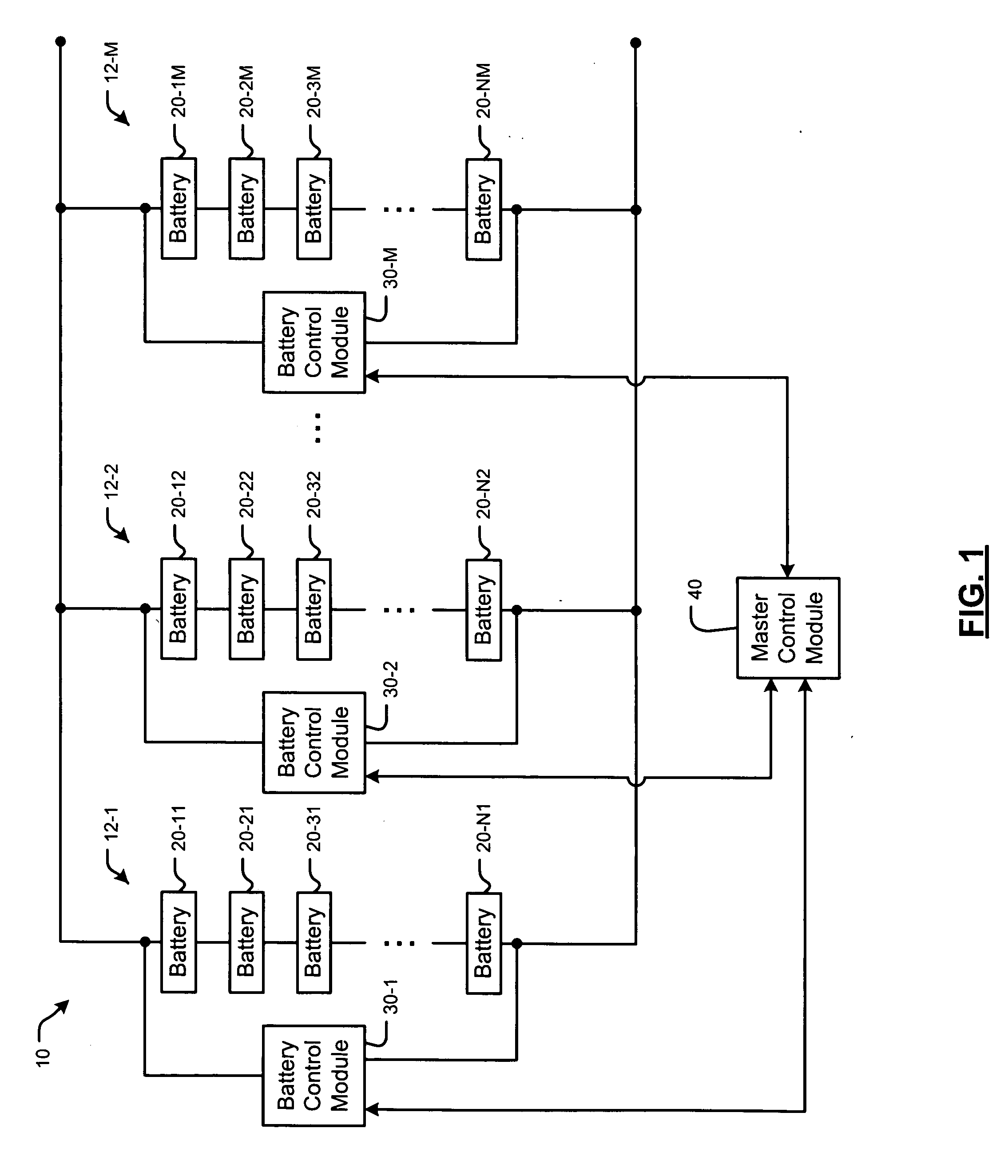
[0022]An exemplary system that can be used to predict the maximum power output of a battery will be shown, although skilled artisans will appreciate that other systems may be used. Referring now to FIG. 1, an exemplary embodiment of a battery system 10 is shown to include M battery subpacks 12-1, 12-2, . . . , and 12-M (collectively battery subpacks 12). The battery subpack...


PUM


Abstract

A battery control module for use with a battery includes a voltage measuring module that measures battery voltage and a current measuring module that measures battery current. A power limit module communicates with the current and voltage measuring modules and once every time period estimates a battery current limit that corresponds with a future time period. The battery current limit is based on a predetermined voltage limit of the battery and a battery current and a battery voltage that correspond with a time period that precedes the future time period.

Description

FIELD OF THE INVENTION[0001]The present invention relates to battery systems, and more particularly to determining power delivery limits for battery systems.BACKGROUND OF THE INVENTION[0002]Battery systems may be used to provide power in a wide variety of applications. Exemplary transportation applications include hybrid electric vehicles (HEV), electric vehicles (EV), heavy duty vehicles (HDV) and vehicles with 42-volt electrical systems. Exemplary stationary applications include backup power for telecommunications systems, uninterruptible power supplies (UPS), and distributed power generation applications.[0003]Examples of the types of batteries that are used include nickel metal hydride (NiMH) batteries, lead-acid batteries, and other types of batteries. A battery system may include a plurality of battery subpacks that are connected in series and / or in parallel. The battery subpacks may include a plurality of batteries that are connected in parallel and / or in series.[0004]Inheren...

Claims


Application Information

Patent Timeline
Patent Type & Authority Applications(United States)
IPC IPC(8): H02J7/00
CPCG01R31/3624H01M10/441G01R31/3675G01R31/3648G01R31/374G01R31/3842Y02E60/10
Inventor MELICHAR, ROBERT J.
Owner CHEVRON TECH VENTURES
Why Eureka
Try Eureka