Load distribution control system and method

a control system and load technology, applied in the direction of digital output to print units, multi-programming arrangements, instruments, etc., can solve the problems of complex control parameters for load distribution, difficult to efficiently distribute loads, and unrealized environment, so as to reduce the number of jobs, and improve the effect of efficiency

Inactive Publication Date: 2008-01-10
HITACHI LTD
View PDF4 Cites 46 Cited by
  • Summary
  • Abstract
  • Description
  • Claims
  • Application Information

AI Technical Summary

Benefits of technology

[0017]The invention can provide a system including a plurality of computers, for distributing loads on the computers wherein the access performance of the computers to a storage device, where data is stored, is enhanced and the computers thereby efficiently process jobs by executing an application program, and where the TAT can be shortened.

Problems solved by technology

Also, since workstations (WS) have become widespread, control parameters for load distribution have become complicated and it is difficult to efficiently distribute loads.
An environment that allows stable job execution is required for all jobs that application programs intend to fulfill, but such an environment has not been realized.
When causes of abnormal job termination prior to the completion of jobs are analyzed, it is found in many cases that a disk, which is a data storage means, has a shortage of capacity, and an operator makes a mistake and instructs the application to select incorrect data.
However, sufficient attention is not paid to disk optimization or stabilization of program processes.
In other words, when an application program for RAID logical designing processes mass data by means of conventional load distribution techniques, the processing of a job to execute the application program sometimes becomes unstable, the job processing time increases, and a computer's access performance to the storage unit where the relevant data is stored sometimes decreases.
If data necessary for job execution does not exist in the storage unit accessed by the computer, there is the possibility, even in the environment where load distribution is realized, that an I / O access by the computer to the storage unit may enter the wait state or become an error.

Method used


Image

  • Load distribution control system and method
  • Load distribution control system and method
  • Load distribution control system and method

Examples


Embodiment Construction

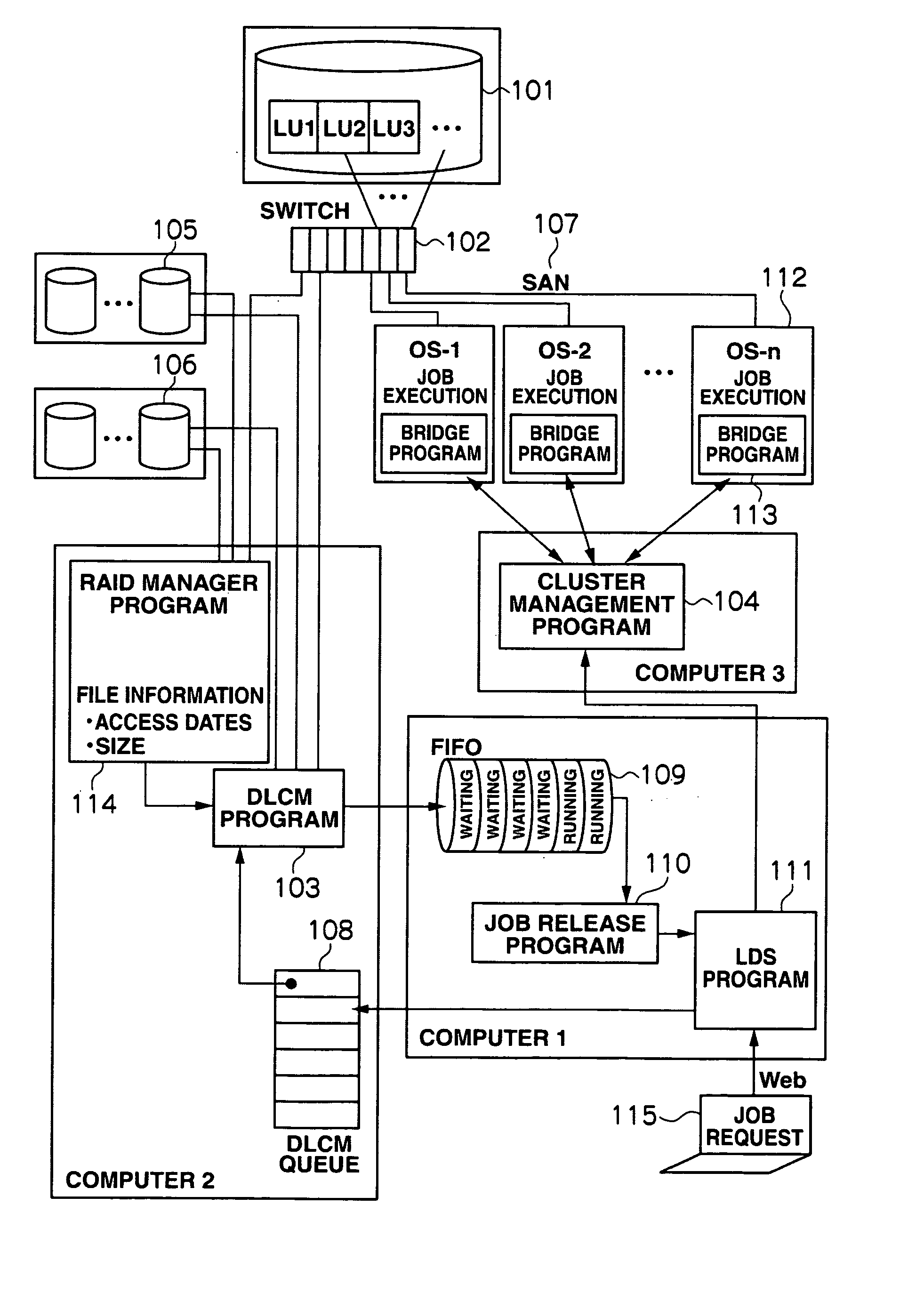
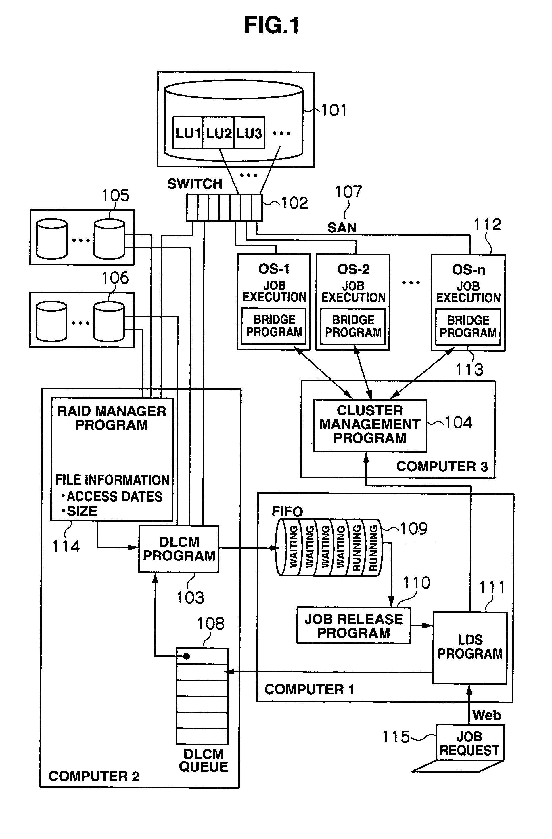
[0033]Embodiments of the invention will be described below with reference to the attached drawings. FIG. 1 is a block diagram of a load distribution control system according to an embodiment of the invention. Referring to FIG. 1, the load distribution control system includes: a first storage unit 101 having a plurality of hard disk drives in array, that are configured according to the RAID (Redundant Arrays of Independent Disks) system and have an interface to which computers can make an I / O access at high speeds; a second storage unit 105 having disk drives of great capacity; a third storage unit 106 having archive disk units; and a group of computers 112 that execute jobs by sending / receiving information to / from the storage unit 101.

[0034]The storage unit 101 has a plurality of hard disk drives using a Fibre Channel interface. The storage unit 101 is connected to a switching hub 102 and, via a SAN (Storage Area Network) 107 as a network, to each computer 112. Storage resources of ...


PUM


Abstract

Processing time for job execution is shortened by using computation capability to the maximum extent possible.
When a user makes a job request, the job request is sent from an LDS program of a first computer to a second computer; the second computer executes data preparation processing and empty area reservation processing with regard to a storage unit (disk A) and stores the results to an the FIFO of the first computer; when the output from the FIFO is transferred via a job release program to the LDS program, the transferred content is then transferred to a third computer; and the third computer selects a computer that should execute the job, from among a group of computers and commands the selected computer to execute the job.

Description

CROSS-REFERENCES TO RELATED APPLICATIONS[0001]This application relates to and claims priority from Japanese Patent Application No. 2006-187997, filed on Jul. 7, 2006, the entire disclosure of which is incorporated herein by reference.BACKGROUND[0002]1. Field of the Invention[0003]The invention relates to a load distribution control system, including a plurality of computers, for having the computers execute jobs by distributing loads for the computers, and also relates to a load distribution control method.[0004]2. Description of Related Art[0005]Recently, various computer load distribution techniques have been suggested (see JP-A-1049504, JP-A-11-3323, and JP-A-10-334057). As computers have achieved high performance, when controlling load distribution, the processing time (Turn Around Time [TAT]) spent to obtain the processing results for an executed job varies considerably depending on whether jobs to be executed by computers are distributed well or not. Also, since workstations (...

Claims


Application Information

Patent Timeline
Patent Type & Authority Applications(United States)
IPC IPC(8): G06F3/12G06F15/00
CPCG06F9/4843G06F2209/508G06F9/505
Inventor OGATA, YOKOSUZUKI, HIDENORI
Owner HITACHI LTD
Why Eureka
Try Eureka