Light guiding structure

a technology of light guiding and structure, applied in the direction of instrumentation, lighting and heating apparatus, planar/plate-like light guides, etc., can solve the problems of bringing the production cost higher, the cost is comparatively more expensive, and the led consumes a large amount of electricity. , to achieve the effect of improving the illumination of the keying uni

Inactive Publication Date: 2008-01-10
LIN TAI YEN
View PDF9 Cites 32 Cited by
  • Summary
  • Abstract
  • Description
  • Claims
  • Application Information

AI Technical Summary

Benefits of technology

[0008]In light of the drawbacks of the above prior arts, the primary objective of the present inve

Problems solved by technology

However, because of the need to use multiple LED for the light-guide plate in this patent, the cost is comparatively more expensive, and the LED consumes a large amount of electricity as well.
Moreover, the addition of convex lens requires relatively more processing procedures during the production, which brings the production cost higher as a result.
On the other hand, by arranging the light source underneath the light-guide plate, the overall thickness of the resulted device is increased as well, hence impeding the miniaturization of the device.
Additionally, because U.S. Pat. No. 5,083,240 has to form groove-like reflector around the parameter of the light guide plate and cut the corner for reflecting some of the light, the light guide plate like that is hard to fabricated, can only be fitted to one specific model,

Method used


Image

  • Light guiding structure
  • Light guiding structure
  • Light guiding structure

Examples


first embodiment

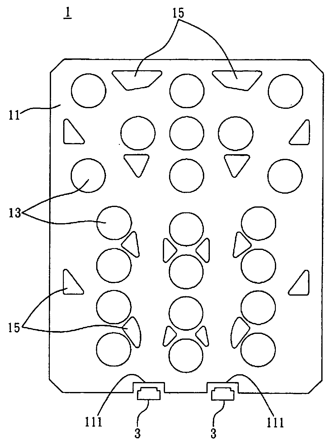
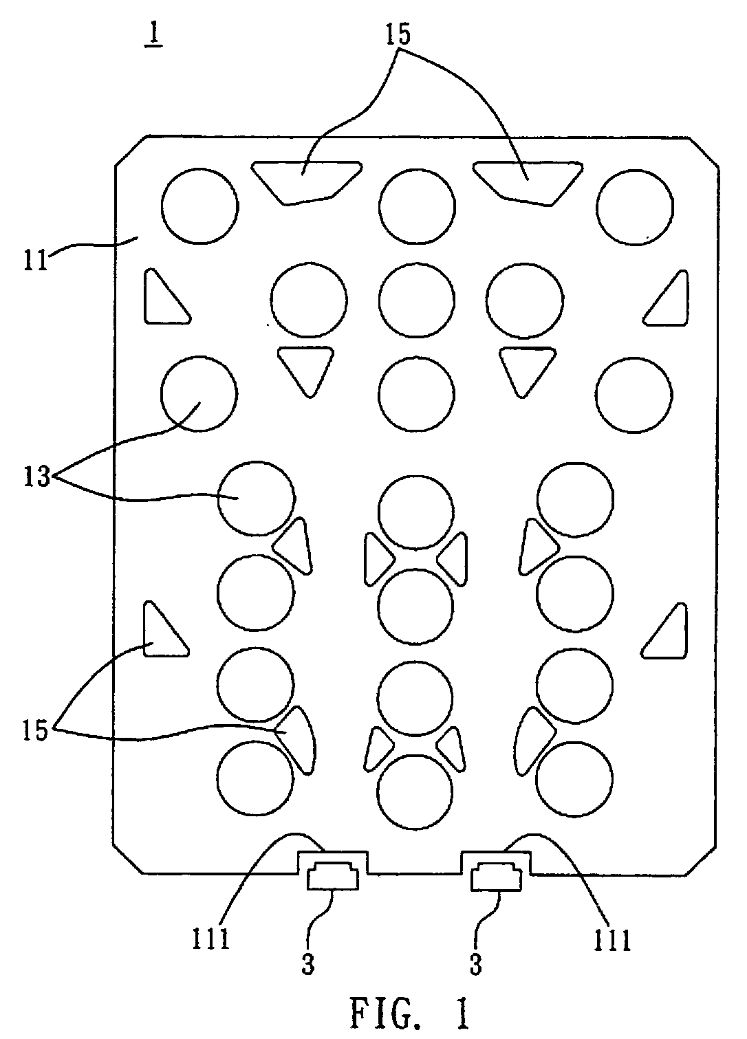
[0032]In a first embodiment, as shown in FIG. 1, the light guiding system 1 may be installed in a portable device having a plurality of keying units (not shown) and a plurality of illuminators 3, such that incident light produced by the illuminators 3 can be transmitted and distributed to each keying unit by the use of the light guiding system 1. Further, the keying units may be exposed from a side of a casing of the portable device. In this embodiment, the light guiding system 1 comprises a light guiding structure 11; a plurality of coupling portions 13 on the light guiding structure 11 for coupling with corresponding keying units; at least an incident portion 111 for receiving incident light produced by the illuminator; and a plurality of light guiding portions 15 for guiding the incident light to each coupling portion 13.

[0033]The light guiding structure 11 of the light guiding system 1 is made of a light-transmittable material selected from the group consisting of gum, rubber, g...

second embodiment

[0041]FIG. 3 and FIGS. 4A to 4B are schematic views depicting a light guiding system 1 in accordance with a second preferred embodiment of the present invention. Most of the structure of the light guiding system 1 of the second preferred embodiment is similar to that of the first preferred embodiment, however the light guiding system 1 of the second preferred embodiment further comprises a cover member 113. In this embodiment, the cover member 113 is placed on the light guiding structure 11 at a location above a side of the incident portion 111 that is corresponding to the illuminator 3. The cover member 113 may be made of a material selected from the group comprising consisting of glass, plastic, polycarbonate (PC), polymethyl methacrylate (PMMA), polystyrene (PS), polyamide (PA), methylmethacrylate-styrene (MS), polybutylene terephthalate (PBT), polyethylene terephthalate (PET), polypropylene (PP), polyvinyl chloride (PVC), acrylonitrile-butadiene-styrene resin (ABS), polyethylene...

third embodiment

[0045]FIGS. 5A to 5E are schematic views depicting a light guiding system in accordance with a third preferred embodiment of the present invention. Most of the structure of the light guiding system 1 of the third preferred embodiment is similar to that of the first preferred embodiment, however the light guiding system 1 of the third preferred embodiment may be equipped with directed lighting (referring to the illuminator 3′ as shown in FIGS. 5A to 5D), or equipped with directed and sided lighting.

[0046]Referring to FIG. 5A, an incident portion 111′ of the light guiding system 1 is formed on the bottom surface at a location corresponding to a illuminator 3′ such as a LED. Arrangement as such may be applied to a particular area required a high intensity of illumination. Furthermore, if the light guiding system 1 is equipped with the directed lighting as well as the sided lighting (referring to the illuminator 3 as shown in FIG. 1), the directed lighting (illuminator 3′) can supplemen...


PUM


Abstract

The present invention discloses a light guiding system, which is applied to a portable or handheld device having at least a keying unit and at least an illuminator. The light guiding system includes a light guiding structure; at least a coupling portion for coupling with a corresponding keying unit of the portable device; at least an incident portion for receiving incident light generated by illuminator; and at least a light guiding portion.

Description

[0001]This application is a Continuation-In-Part of copending application Ser. No. 11 / 480,422 filed on Jul. 5, 2006, the entire contents of which are hereby incorporated by reference and for which priority is claimed under 35 U.S.C. §120.FIELD OF THE INVENTION[0002]The present invention relates to light guiding systems, and more particularly, to a light guiding system applied to a portable or handheld device equipped with at least a keying unit and at least an illuminator.BACKGROUND OF THE INVENTION[0003]Nowadays, portable or handheld electronic devices from the video conferencing sector, information sector, communication sector, home appliance sector, and consumer sector; such as mp3 players, cell phone, personal digital assistant (PDA), and remote controller have become an indispensable part of our daily life, but sometimes the need to use the devices in occasions without sufficient lighting has always been a nuisance. To allow the portable or handheld electronic devices to be use...

Claims


Application Information

Patent Timeline
IPC IPC(8): F21V7/04
CPCG02B6/0018G02B6/0045G02B6/0035G02B6/0021
Inventor LIN, TAI-YEN
Owner LIN TAI YEN
Why Eureka
Try Eureka