DC power transmisson system of voltage source converter using pulse-interleaving auxiliary circuit

a technology of auxiliary circuits and dc power transmission, which is applied in the direction of electric variable regulation, process and machine control, instruments, etc., can solve the problems of large switching loss, large consumption of reactive power from the interconnected ac system when it operates, and limitation of ac power transmission in the long distance power transmission

Inactive Publication Date: 2008-01-10
MYONGJI UNIV IND & ACAD COOPERATION FOUND
View PDF3 Cites 40 Cited by
  • Summary
  • Abstract
  • Description
  • Claims
  • Application Information

AI Technical Summary

Benefits of technology

[0017]In order to achieve the above-described objects of the present invention, there is provided a converter system comprising: an IGBT converter for converting an AC power to a DC power or the DC power to the AC power; an open Y-Y transformer and a Y-Δ transforme...

Problems solved by technology

However, the AC power transmission has a limitation in the long distance power transmission due to an inductance in the power transmission line and a capacitance between a power transmission line and a ground.
The HVDC system employing thyristor, which has no turn-off capability at the gate, consumes reactive power from the interconnected AC system when it operates.
While the PWM converter has a simple system configuration using the single bridge, a switching loss is large due to multiple switching of each of the switching elements per one AC cycle.
Therefore, the PWM converter is not suitable for a large capacity system.
However, this scheme is disadvantageous in that a size of the sys...

Method used


Image

  • DC power transmisson system of voltage source converter using pulse-interleaving auxiliary circuit
  • DC power transmisson system of voltage source converter using pulse-interleaving auxiliary circuit
  • DC power transmisson system of voltage source converter using pulse-interleaving auxiliary circuit

Examples


Embodiment Construction

[0033]The present invention will now be described in detail with reference to the accompanied drawings.

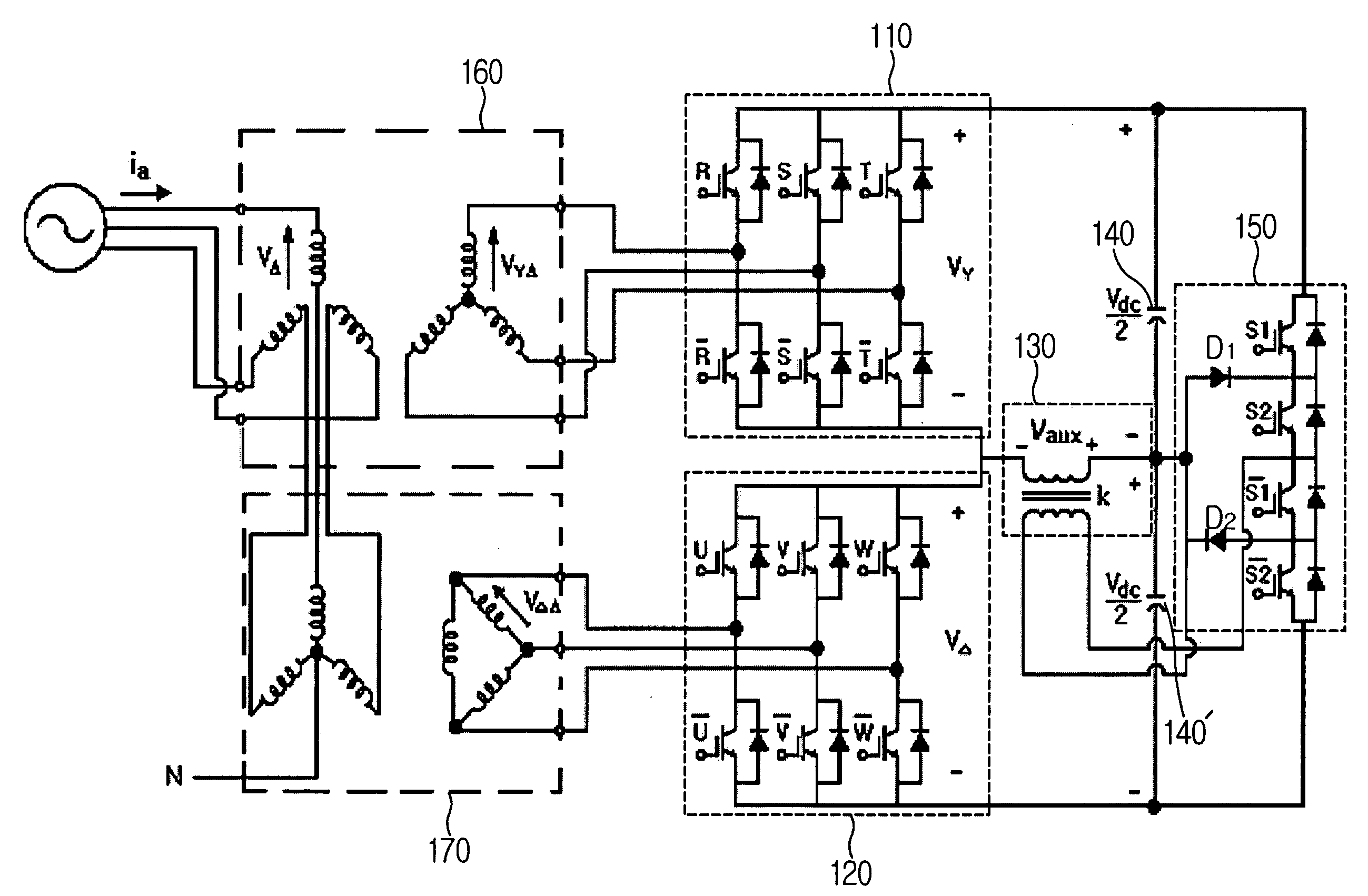
[0034]FIG. 4 is a diagram illustrating a 36-step converter system using a DC auxiliary circuit in accordance with the present invention.

[0035]The 36-step converter system shown in FIG. 4 comprises a first converter 110 connected to a Y-Y transformer 160, a second converter 120 connected to a Y-Δ transformer 170, an injection transformer 130, first and second DC capacitors 140 and 140′, and a 3-level half bridge circuit 150.

[0036]A ground terminal of the first converter 110 and an output terminal of the second converter 120 are connected to a first terminal of a primary winding of the injection transformer 130, and a connecting point of the first and second DC capacitors 140 and 140′ serially connected between an output terminal of the first converter 110 and a ground terminal of the second converter 120 is connected to a second terminal of the primary winding of the injection trans...


PUM


Abstract

A DC power transmission system of a voltage source converter using a pulse-interleaving auxiliary circuit is disclosed.
The converter system of the present invention comprises an IGBT converter for converting an AC power to a DC power or the DC power to the AC power; an open Y-Y transformer and a Y-Δ transformer for stepping up or stepping down the AC power having a predetermined magnitude; a capacitor for dividing a DC voltage; and a transformer and a half-bridge auxiliary circuit for overlapping a pulse type input voltage to increase a number of pulses of an output waveform.
In accordance with the present invention, the normal transformer is used instead of a tapped transformer to reduce the size thereof and to obtain an accurate transformer ratio, the 3-level half bridge is used instead of the H-bridge to reduce the switching loss in order to increase the number of pulses of the output waveform by superposing the voltage in the form of the pulse using the auxiliary transformer and the bridge circuit.

Description

BACKGROUND OF THE INVENTION[0001]1. Field of the Invention[0002]The present invention relates to a DC power transmission system, and in particular to a DC power transmission system using a voltage source converter with a pulse-interleaving auxiliary circuit comprising a transformer and a 3-level half bridge.[0003]2. Description of Prior Art[0004]Generally, an AC voltage and an AC current being outputted from a generator has a low voltage and a high current. The AC voltage and the AC current are subjected to a long distance power transmission in a form of a low current while maintaining a high voltage using a high voltage transformer or a ultra-high voltage transformer due to a conductor loss by the high current during the power transmission. However, the AC power transmission has a limitation in the long distance power transmission due to an inductance in the power transmission line and a capacitance between a power transmission line and a ground. In order to overcome the above-desc...

Claims


Application Information

Patent Timeline
IPC IPC(8): H02J3/36
CPCH02M7/19Y02E60/60H02M7/7575H02M7/487H02J3/06
Inventor HAN, BYUNG MOON
Owner MYONGJI UNIV IND & ACAD COOPERATION FOUND
Why Eureka
Try Eureka