Dialysis catheter

a catheter and dialysis technology, applied in the field of catheters, can solve the problems of adversely affecting the blood flow through the catheter during dialysis, blood clots at the catheter tip, blood clots in the lumen, etc., and achieve the effect of preventing the withdrawal of fluid

Inactive Publication Date: 2008-01-10
REX MEDICAL LP
View PDF32 Cites 48 Cited by
  • Summary
  • Abstract
  • Description
  • Claims
  • Application Information

AI Technical Summary

Benefits of technology

[0009] The present invention overcomes the problems and deficiencies of the prior art. The present invention provides a dialysis catheter comprising an inner tube having a distal end, a first lumen and a first delivery opening communicating with the first lumen for delivery of fluid to a patient and a second outer tube having a distal end, a second lumen and a first withdrawal opening communicating with the second lumen to withdraw fluid from a patient. The inner tube is positioned within the outer tube and the inner and outer tubes are relatively movable between a first and second position. In the first position, the distal end of the inner tube is spaced a first distance from the distal end of the outer tube to enable withdrawal of fluid and in the second position the withdrawal opening is blocked to prevent withdrawal of fluid from the patient.

Problems solved by technology

This can cause blood clotting in the lumens which can affect blood flow through the catheter during dialysis.
Consequently, there could be a loss of heparin lock which can cause blood clots at the catheter tip and can adversely affect blood flow through the catheter during dialysis.
This fibrin growth, caused by the body's attempt to reject the catheter as a foreign body, could result in blocking of the holes in the sidewalls of the catheter.
These sidewall holes communicate with the catheter lumens for delivery or withdrawal of blood and therefore blocking of the holes can adversely affect blood flow.

Method used


Image

  • Dialysis catheter
  • Dialysis catheter
  • Dialysis catheter

Examples


Embodiment Construction

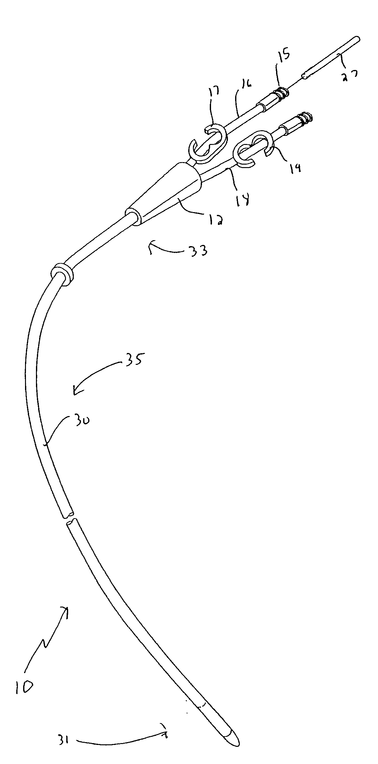
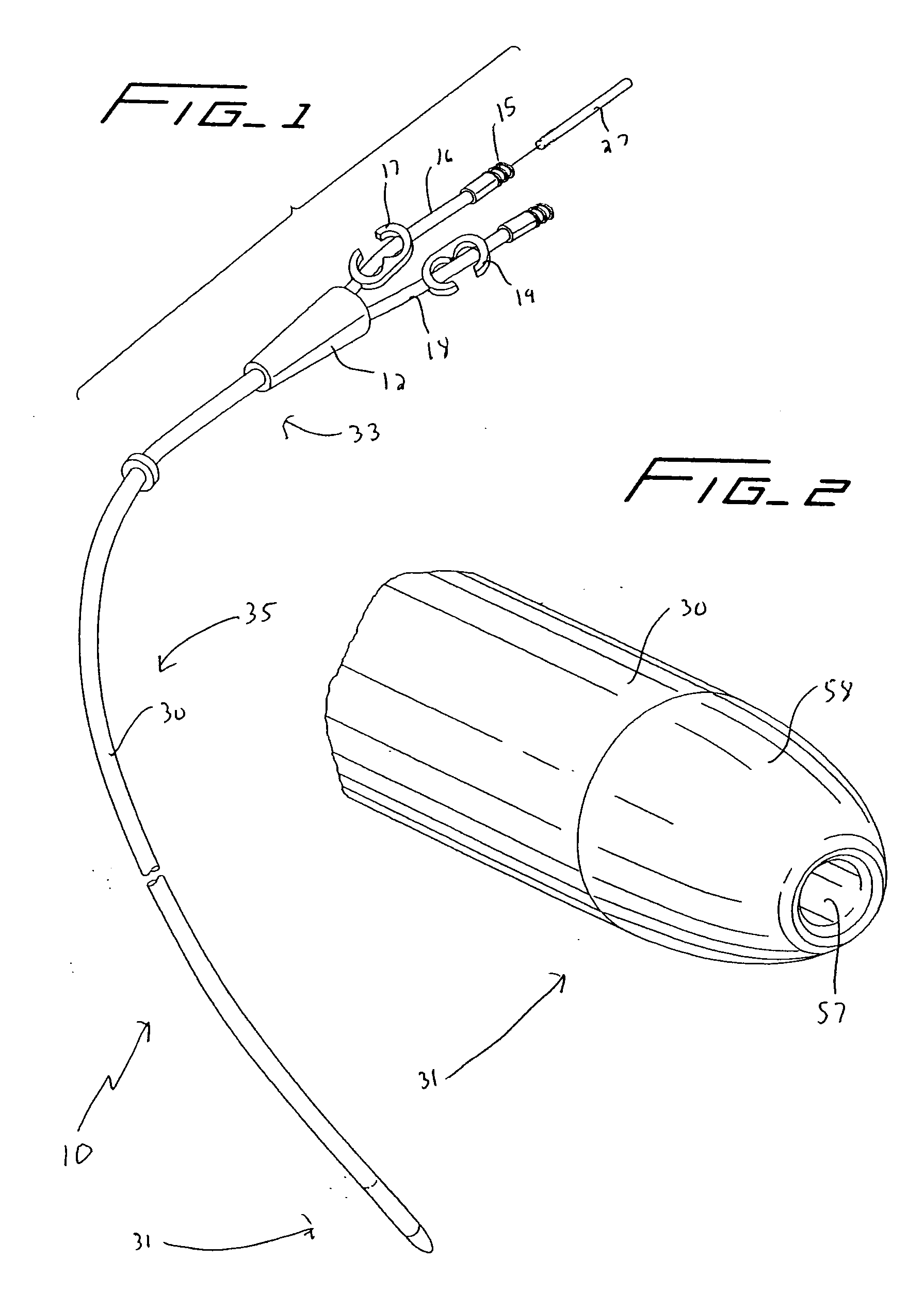
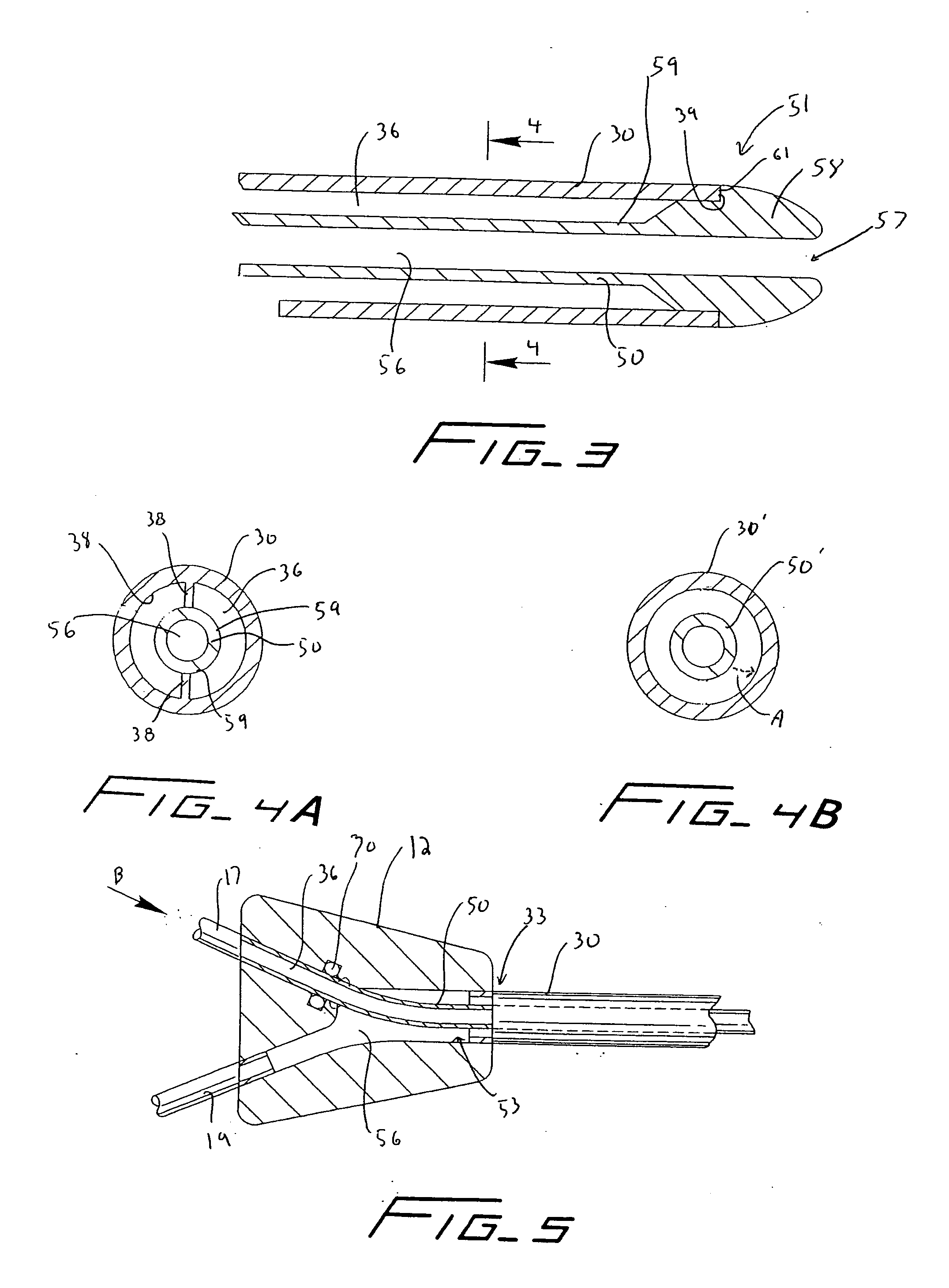
[0046] Referring now in detail to the drawings where like reference numerals identify similar or like components throughout the several views, the first embodiment of the catheter of the present invention is designated generally by reference numeral 10. The catheter 10 is typically inserted into an area of high velocity blood flow to ensure sufficient blood can be transported from the body for dialysis. FIG. 15 illustrates the catheter 10 inserted through the right internal jugular vein “a”, into the superior vena cava “b”, and into the right atrium “c”. The catheter 10 can alternately be inserted (not shown) into the left internal jugular vein, into the superior vena cava and into the right atrium “c”. Insertion into the right atrium, from either the right or left side provides the necessary high blood flow to the dialysis machine. The catheter can also be inserted into other areas of the body and through other access sites. Note that the catheter is sufficiently flexible to enable...


PUM


Abstract

A catheter comprising an inner tube having a distal end, a first lumen and a first delivery opening communicating with the first lumen for delivery of fluid to a patient and a second outer tube having a distal end, a second lumen and a first withdrawal opening communicating with the second lumen to withdraw fluid from the patient. The inner tube is positioned within the outer tube and the inner and outer tubes are relatively movable between a first and second position. In the first position, the distal end of the inner tube is spaced a first distance from the distal end of the outer tube to enable withdrawal of fluid and in the second position the withdrawal opening is blocked to prevent withdrawal of fluid from the patient.

Description

[0001] This application claims priority from provisional application No. 60 / 629,997, filed Nov. 22, 2004.BACKGROUND [0002] 1. Technical Field [0003] This application relates to a catheter and more particularly to a multi-lumen catheter which facilitates hemodialysis. [0004] 2. Background of Related Art [0005] Hemodialysis is a well known method of providing renal (kidney) function by circulating blood. The kidneys are organs which function to extract water and urea, mineral salts, toxins, and other waste products from the blood with filtering units called nephrons. From the nephrons the collected waste is sent to the bladder for excretion. For patients having one or both defective kidneys, the hemodialysis procedure is life saving because it provides a machine to simulate the function of the kidneys. [0006] In the hemodialysis procedure, blood is withdrawn from the patient's body through a catheter or tube and transported to a dialysis machine, also commonly referred to as a kidney ...

Claims


Application Information

Patent Timeline
Patent Type & Authority Applications(United States)
IPC IPC(8): A61M3/00
CPCA61M25/0029A61M25/0069A61M1/3661A61M2025/0031A61M2025/0039A61M25/0075
Inventor LEEDLE, JOHN D.MCGUCKIN, JAMES F. JR.
Owner REX MEDICAL LP
Why Eureka
Try Eureka