Sanitary check valve

a check valve and sanitary technology, applied in the field of valves, can solve the problems of large waste of production time and money, system may not be sterile, puddle may not attain a sufficient time-temperature profile, etc., and achieve the effect of greater rigidity

Inactive Publication Date: 2008-01-17
ZELSON LARRY SAUL
View PDF20 Cites 6 Cited by
  • Summary
  • Abstract
  • Description
  • Claims
  • Application Information

AI Technical Summary

Benefits of technology

[0021] The sanitary check valve of the present invention comprises two components: a stationary portion, termed the valve seat plate, having sufficient rigidity to resist the force of forward flow and back pressure, and a flexible portion, termed the molded elastomer valve body, serving as a combination flange gasket, valve plug, valve sealing spring system, and visual orientation indicator. As assembled, the valve is not much thicker than a standard flange gasket and is therefore readily designed into new piping systems, retrofitted into existing piping systems, and removed and re-installed for replacement during routine preventative maintenance or in the event of material failure.
[0026] The valve plug, at the center of the valve body, aligns with the valve port of the valve seat plate and is shaped to seal the valve port tightly and repeatable by interfacing against the valve seat. The valve plug optionally includes a core for greater rigidity, as may be required depending on the material of construction and diameter of the valve plug.

Problems solved by technology

If a puddle of liquid were to be retained anywhere within the piping system, this puddle may not attain a sufficient time-temperature profile during sterilization to kill any potential contaminating organisms, and as a result the system may not be sterile.
Lack of sterility can cause the loss of a entire batches of product and large amounts of wasted production time and money.
Further, if a system is contaminated during production, no pipe fittings can be disconnected to replace a component until another sterilization has been completed without jeopardizing the safety of personnel.
Thus, a valve which is not easily accessible for maintenance or replacement would be a liability.
When both the stationary valve seat and the moving valve plug are made of metal or another hard material, this rapid flutter will inevitably result in chattering, creating an annoying noise for nearby workers and possibly doing harm to the components of the valve.
This creates two problems.
First, there is an annular crevice between the valve seat holder and the inside pipe wall, extending inwardly from each end of the valve back to the corresponding o-ring, which is not readily cleanable and sterilizable.
Second, in practice, these o-rings do not seal well, since the internal surface of the pipe or tube is not design for this type of application and is therefore not of sufficient uniformity.
The resultant leakage past the o-rings creates either a leak out of the flange or necessitates the addition of a flange gasket.
Further, any process fluid leaking behind the o-rings presents a much more serious risk of contamination due to the complete inability to clean and sterilize this area bounded by the pipe wall, the valve body, the o-rings, and the flange gasket.
Additionally, this valve provides no visual indicator of flow direction or that it is in fact installed at all, and in practice it is sometimes required to pull apart the mating pipe ends just to verify the existence and proper installation of the valve.
However, the “Style 3SC” valve includes the same o-ring configuration as the “Style SCV” valve and therefore suffers from the same disadvantages and problems.
This valve, too, lacks any visual means to indicate that it is installed at all, or that it is installed in the correct flow direction.
However, this valve also includes a shroud around the valve plug having an outside diameter almost as large as the inside diameter of the pipe or tube into which it fits, thus creating a potential crevice with its inherent cleaning and sterilization problems.
Also, this valve lacks any visual means to indicate that it is installed at all, or that it is installed in the correct flow direction.

Method used


Image

  • Sanitary check valve
  • Sanitary check valve
  • Sanitary check valve

Examples


Embodiment Construction

[0055] The following detailed description is of the best presently contemplated mode of carrying out the invention. The description is not intended in a limiting sense, and is made solely for the purpose of illustrating the general principles of the invention. The various features and advantages of the present invention may be more readily understood with reference to the following detailed description taken in conjunction with the accompanying drawings.

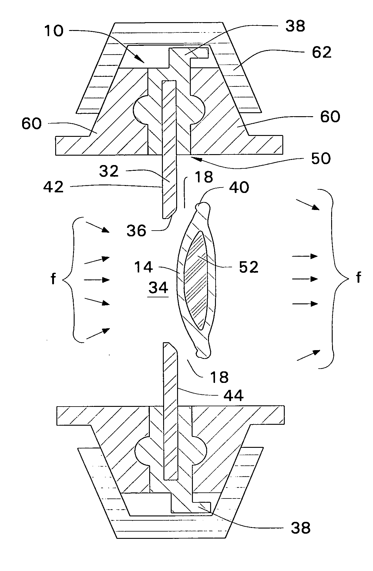
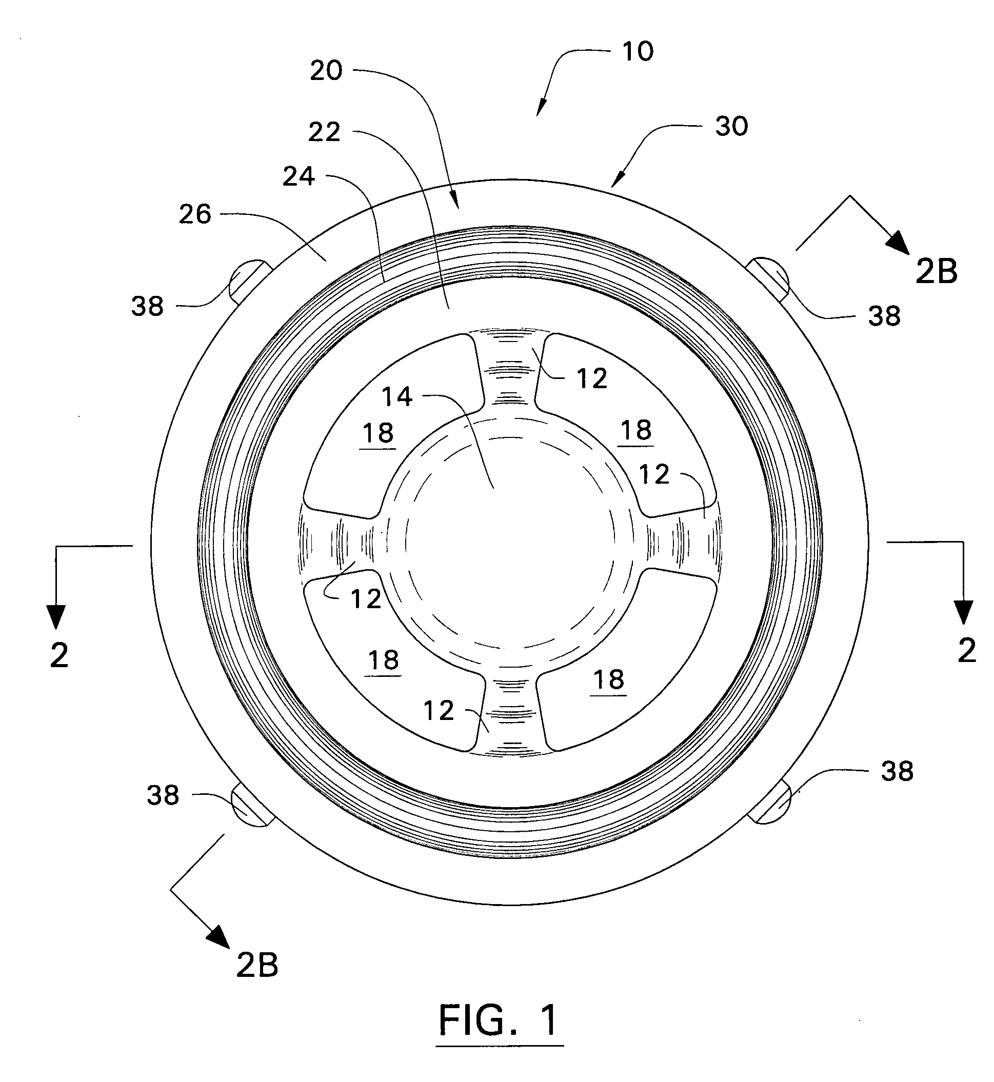
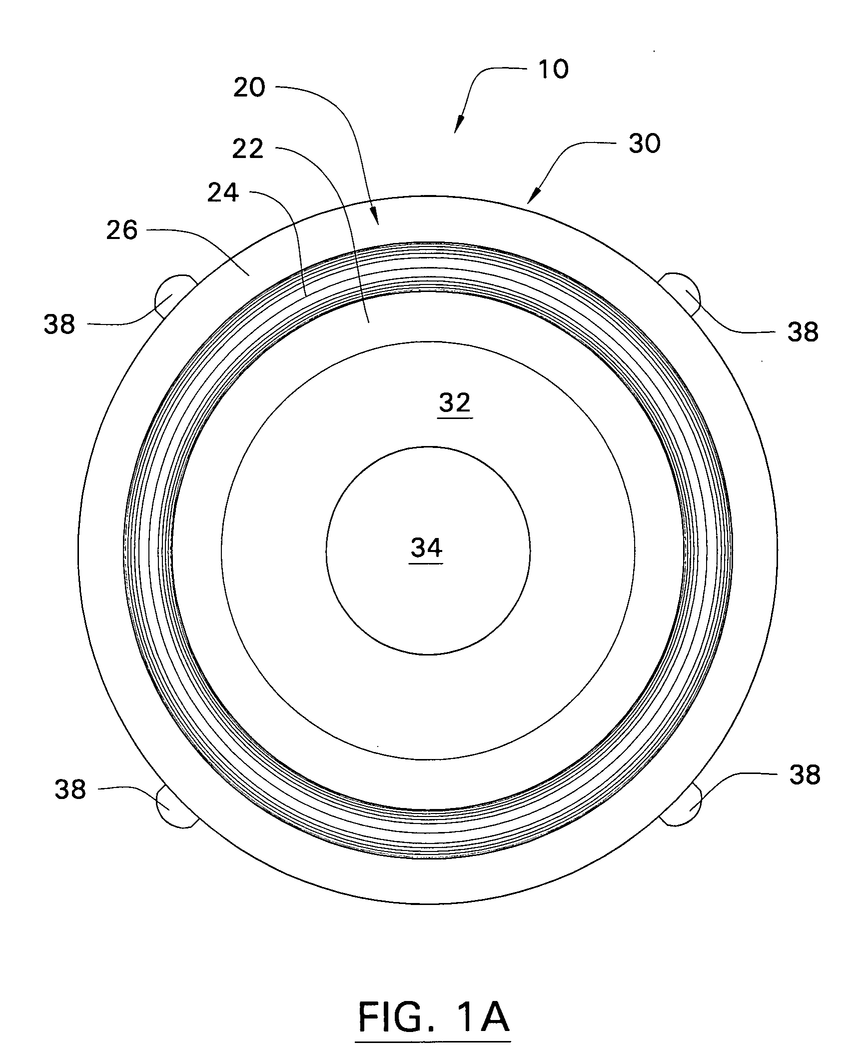
[0056] Referring now to the drawings in detail, where like numerals refer to like parts or elements, there are illustrated seven different embodiments of the sanitary check valve device 10 of the present invention. The most basic embodiment, having a circular concentric valve plug 14 supported by four flexible retaining arms 12 and a fully drainable geometry when mounted in vertical piping, is shown in FIGS. 1 through 3. An alternate embodiment having the same valve plug 14 but having only three retaining arms 12 is shown in FIG. 4....


PUM


Abstract

A check valve adapted for mounting between any flanges and specifically between sanitary flanges in a piping system, the check valve comprising a stationary portion and a flexible portion; the single-piece rigid stationary portion including and supporting a valve seat; the single-piece molded elastomeric flexible portion including a flange gasket, a valve plug, flexible retaining arms for guiding and securing the valve plug movement with respect to the valve seat, and a visual means to indicate that the check valve is installed, permits flow in the desired direction, and is drainable; the check valve being fully cleanable and sterilizable in situ by flow-through methods and having at least one embodiment that is fully drainable when mounted in any orientation.

Description

CROSS-REFERENCE TO RELATED APPLICATIONS [0001] This application is a continuation of U.S. patent application Ser. No. 10 / 860,252, filed on Jun. 3, 2004, which claimed the benefit of the filing date of U.S. Provisional Patent Application No. 60 / 477,193, filed on Jun. 10, 2003.BACKGROUND OF THE INVENTION [0002] The present invention relates to valves used to restrict the direction of flow in process piping. More specifically, the present invention relates to a check valve which can be inserted between two standard flanges in any process piping system. Yet more specifically, the present invention relates to a simple, low cost, easily installed, replaceable check valve particularly adapted for sanitary piping systems used in the food, dairy, pharmaceutical, and biotechnology industries. [0003] The use of check valves in sanitary piping systems is well known in the prior art. Although prior devices have been designed to accomplish the purpose of maintaining unidirectional flow while meet...

Claims


Application Information

Patent Timeline
Patent Type & Authority Applications(United States)
IPC IPC(8): F16K15/14
CPCF16K15/144Y10T137/7857
Inventor ZELSON, LARRY
Owner ZELSON LARRY SAUL
Why Eureka
Try Eureka