
Fence

a technology of fences and pillars, applied in the field of fences, can solve the problems of rot or deterioration affecting the appearance of conventional wooden fences, and requiring periodic maintenance, so as to increase the strength and/or rigidity of components, facilitate rapid and easy construction, and facilitate formation

Inactive Publication Date: 2008-01-17
LIFETIME PRODUCTS
View PDF99 Cites 22 Cited by
  • Summary
  • Abstract
  • Description
  • Claims
  • Application Information

AI Technical Summary

Benefits of technology

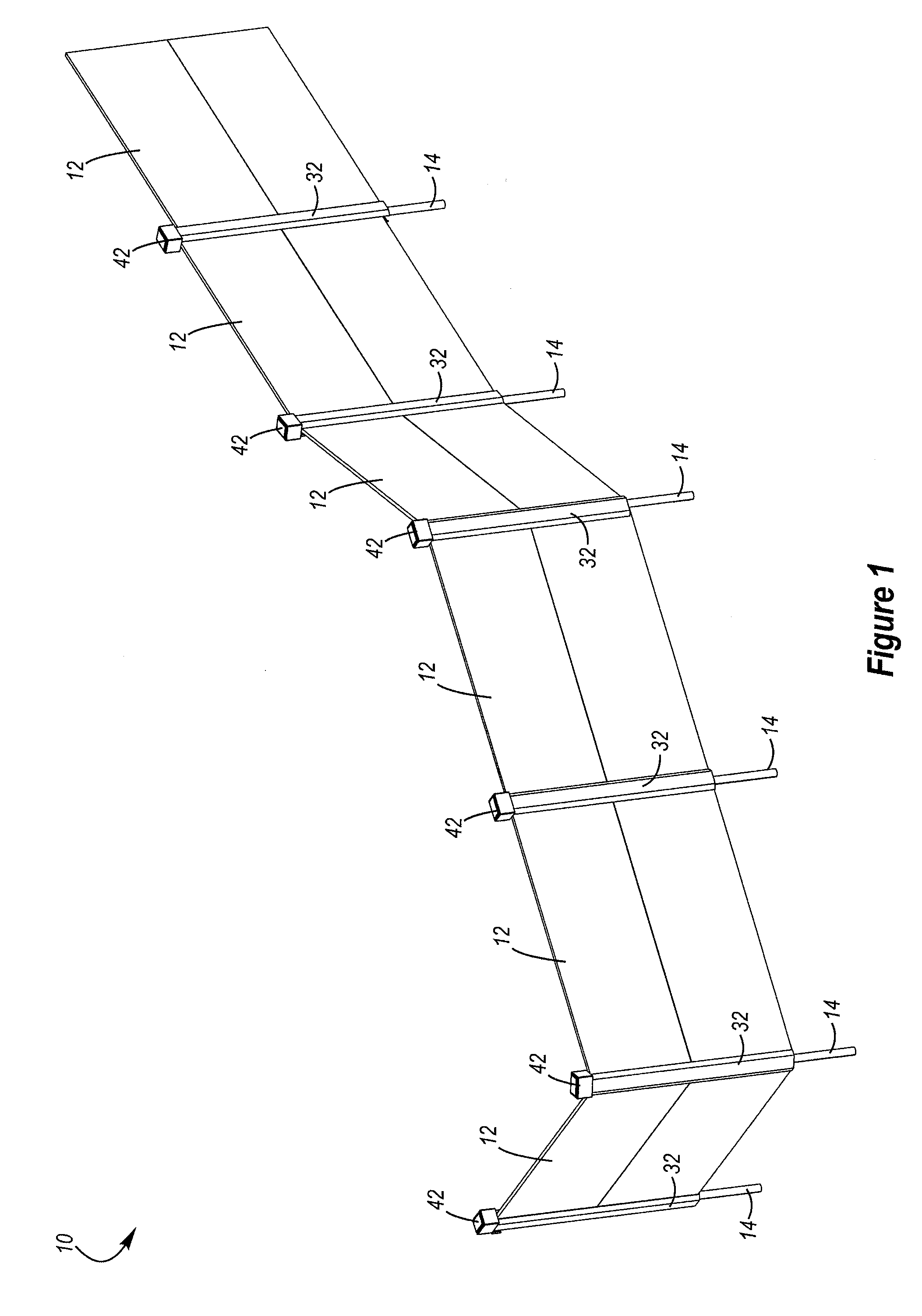
[0011] One aspect is a fence that may be constructed from relatively lightweight materials. For example, all or a portion of the fence may be constructed from plastic. Advantageously, the lightweight materials may allow the fence to be easily moved and transported. The lightweight materials may also allow the fence to be easily installed and removed.
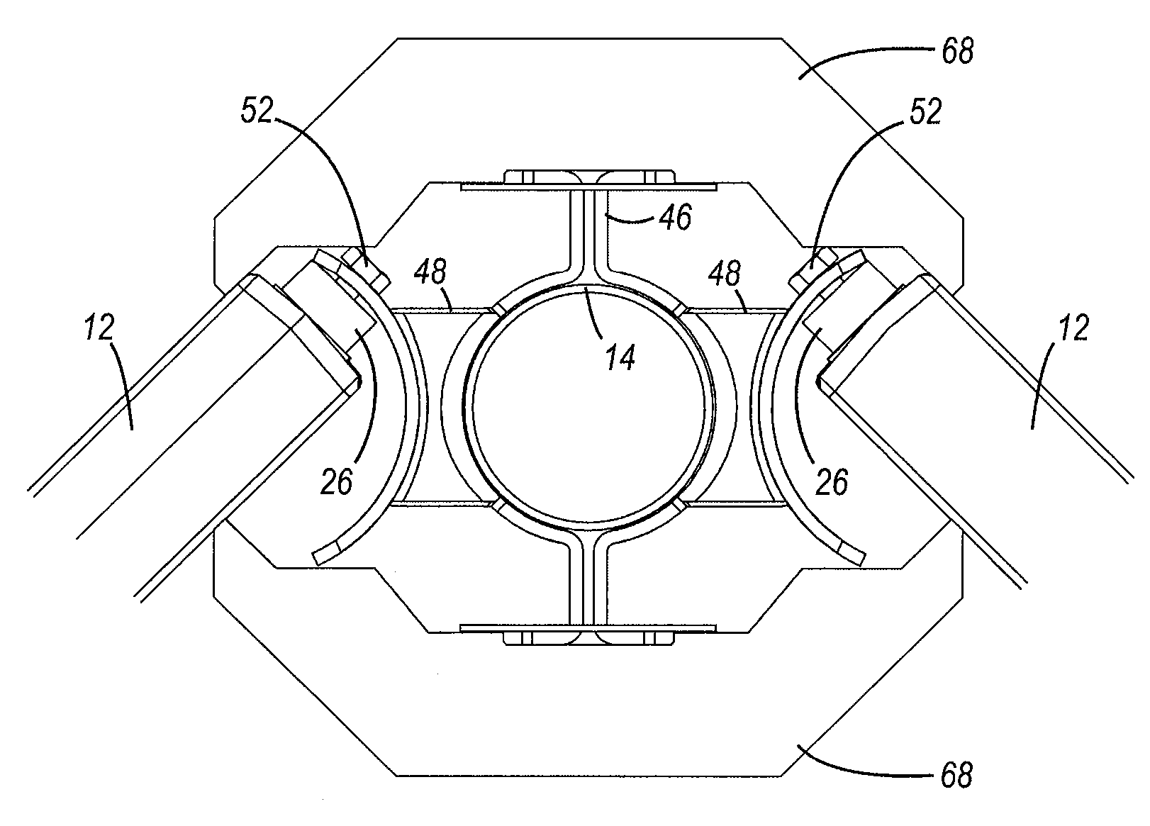
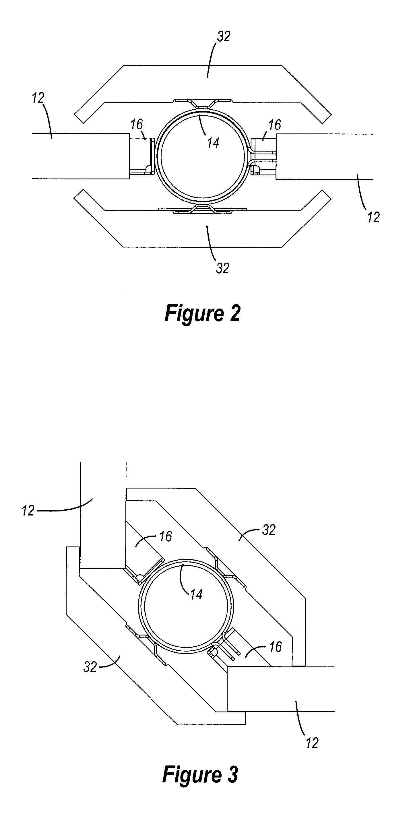
[0035] A still further aspect is a fence that may include an attachment mechanism which may be used to connect one or more fence sections to a support. The attachment mechanism may include a first portion that is sized and configured to be adjustably connected to a first fence section and / or the support; and a second portion that is sized and configured to be adjustably connected to a second fence section and / or the support. In particular, the first portion preferably includes a plurality of openings that may receive a first fastener, which may be used to adjustably connect the first portion to a first tube or rod; and the second portion preferably includes a plurality of openings that may receive a second fastener, which may be used to adjustably connect the second portion to a second tube or rod. The first and second tubes may each include one or more openings (such as elongated slots), which may receive the first and second fasteners and may provide further adjustability. The first tube or rod may be telescopically coupled to and / or form part of a support structure of a first fence section; and the second tube or rod may be telescopically coupled to and / or form part of a support structure of a second fence section. The first and second portions of the attachment mechanism may also include one or more openings that may be aligned to receive one or more fasteners to interconnect the first and second portions. For example, the first and second portions may include openings that may receive a fastener (such as a rivet) that may pivotally or otherwise connect the first and second portions, which may allow the first and second portions to form at least part of a clamp. In addition, the first and second portions may include openings that may receive a fastener (such as a screw) that may allow the attachment mechanism to be clamped to the support. Desirably, this may allow the attachment mechanism to be quickly and easily connected to and disconnected from the support.

Problems solved by technology

Conventional wooden fences typically have an attractive initial appearance, but maintaining that initial appearance may require significant effort because of exposure to the elements.
In addition, conventional wooden fences may rot or deteriorate over time.
Therefore, conventional wooden fences frequently require periodic maintenance, which may be time consuming and expensive.
Furthermore, conventional wooden fences may be difficult and time consuming to install, which may also increase costs and expenses.
Vinyl fences, however, may deteriorate and / or discolor over time.
For example, many conventional vinyl fences can become brittle after prolonged exposure to sunlight.
Moisture, such as water from a sprinkling system, may also discolor many conventional vinyl fences.
Further, many conventional vinyl fences are not very strong and may be damaged from various types of impacts.
In addition, many conventional vinyl fences are not very secure or stable and may be damaged, for example, by a sudden gust of wind.
Disadvantageously, it may be difficult and expensive to repair and / or replace portions of a conventional vinyl fence.

Method used


Image

  • Fence
  • Fence
  • Fence

Examples


Embodiment Construction

[0010] A need therefore exists for a fence that eliminates or diminishes the above-described disadvantages and problems.

[0011] One aspect is a fence that may be constructed from relatively lightweight materials. For example, all or a portion of the fence may be constructed from plastic. Advantageously, the lightweight materials may allow the fence to be easily moved and transported. The lightweight materials may also allow the fence to be easily installed and removed.

[0012] Another aspect is a fence that may be constructed from blow-molded plastic. Advantageously, the fence may contain hollow interior portions that are formed during the blow-molding process, which may allow a light-weight fence to be constructed. In addition, if the fence is constructed from blow-molded plastic, then the blow-molded plastic portions may be relatively easily formed into many different desired shapes, sizes, configurations and designs depending, for example, upon the intended use and / or configuratio...


PUM


Abstract

A fence may include one or more sections that are connected to supports, such as fence posts, by attachment members. The attachment members preferably allow the fence sections to be disposed at various angles, elevations and distances from the supports. Advantageously, this may allow the fence to be disposed in a wide variety of configurations and arrangements. This may also allow the fence to be used in a number of different environments, such as on sloped and uneven surfaces. In addition, the fence may be relatively quickly and easily installed because of the readily adjustable connections of the fence sections and supports. The fence may further include other components such as covers, caps, gates and locking assemblies, if desired.

Description

CROSS-REFERENCE TO RELATED APPLICATIONS [0001] This application claims priority to and the benefit of U.S. provisional patent application Ser. No. 60 / 830,470, which was filed on Jul. 11, 2006 and entitled FENCE. [0002] This application claims priority to and the benefit of U.S. provisional patent application Ser. No. 60 / 847,169, which was filed on Sep. 25, 2006 and entitled FENCE. [0003] This application claims priority to and the benefit of U.S. provisional patent application Ser. No. 60 / 883,141, which was filed on Jan. 2, 2007 and entitled FENCE. [0004] These applications are incorporated by reference in their entireties.BACKGROUND OF THE INVENTION [0005] 1. Field of the Invention [0006] The present invention generally relates to fences and, in particular, to fences constructed from metal and / or plastic. [0007] 2. Description of Related Art [0008] Conventional fences are made from materials such as wood. Conventional wooden fences typically have an attractive initial appearance, b...

Claims


Application Information

Patent Timeline
IPC IPC(8): E04H17/16E04H17/00
CPCE04H2017/1491E04H17/168E04H17/1448
Inventor HOWE, RICHSTANFORD, CARL R.WATSON, NEILLINDEMAN, CLARISSASTRONG, L. CURTISSTEED, BRENT
Owner LIFETIME PRODUCTS
Learn More