
System and method for predictive pulse modulation in display applications

a display system and pulse modulation technology, applied in the direction of instruments, static indicating devices, etc., can solve the problems of high power consumption, short useful life span, and need for color separation filtering

Inactive Publication Date: 2008-01-17
TEXAS INSTR INC
View PDF4 Cites 68 Cited by
  • Summary
  • Abstract
  • Description
  • Claims
  • Application Information

AI Technical Summary

Benefits of technology

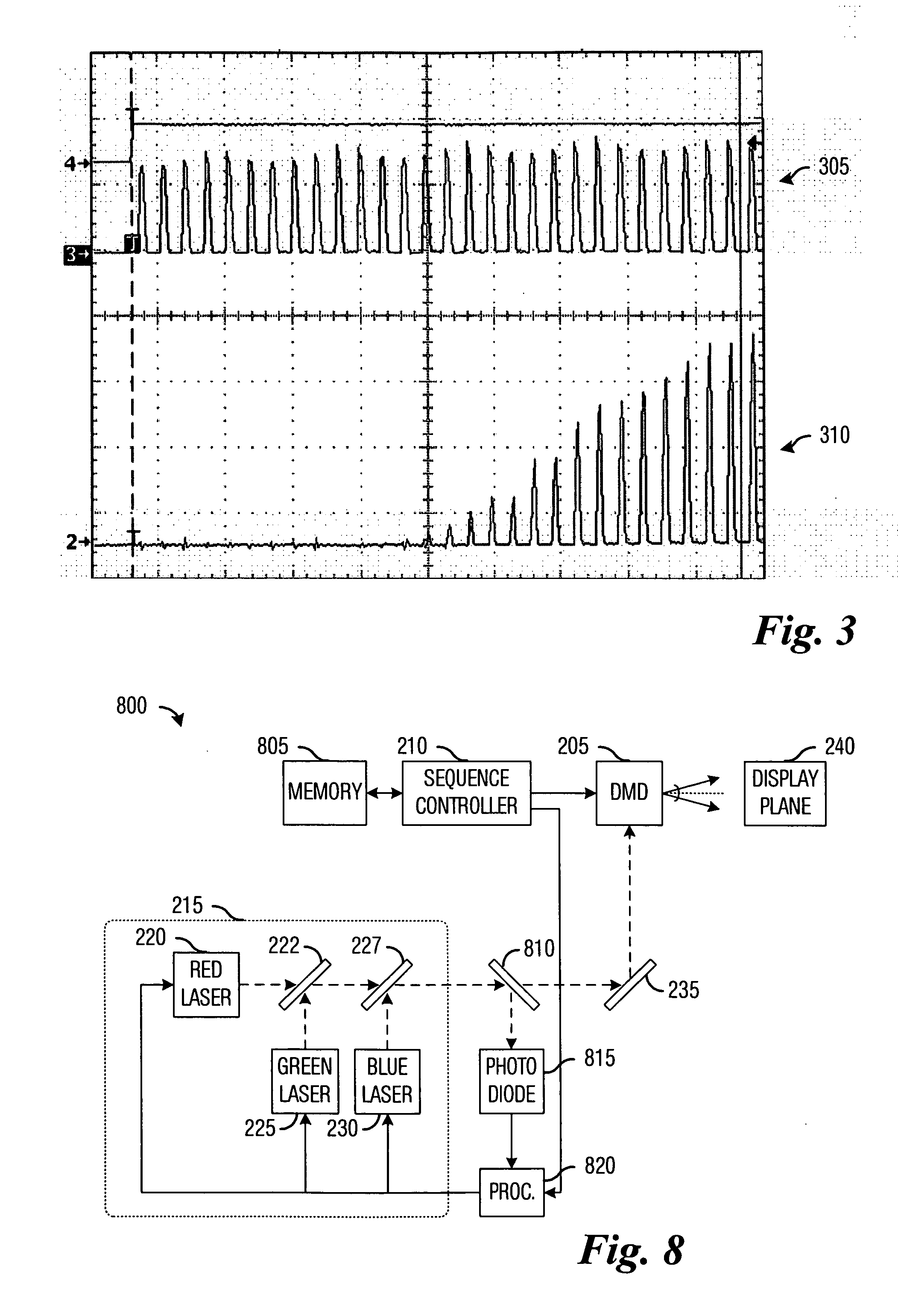
[0012]An advantage of a preferred embodiment of the present invention is that the output of the solid-state light source can be adjusted based upon the recent optical power output and / or usage history of the solid-state light source. This method can allow for the optimization of the output of the solid-state light source to meet light intensity requirements in display applications.

Problems solved by technology

However, due to disadvantages such as slow turn on times, short useful life spans, high power consumption, need for color separation filtering, and so forth, electric arc lamp sources are being replaced by solid-state light sources, such as laser diodes and light emitting diodes.
One disadvantage of the prior art is that the light produced by a solid-state light source may not instantaneously emit with the application of a drive current.
Therefore, there can be a degree of uncertainty in the light produced by the solid-state light source.
Another disadvantage of the prior art is that the light produced by the solid-state light source may not be linear over the time that the drive current is being applied.
This can further lead to uncertainty in the light produced by the solid-state light source.

Method used


Image

  • System and method for predictive pulse modulation in display applications
  • System and method for predictive pulse modulation in display applications
  • System and method for predictive pulse modulation in display applications

Examples


Embodiment Construction

[0023]The making and using of the presently preferred embodiments are discussed in detail below. It should be appreciated, however, that the present invention provides many applicable inventive concepts that can be embodied in a wide variety of specific contexts. The specific embodiments discussed are merely illustrative of specific ways to make and use the invention, and do not limit the scope of the invention.

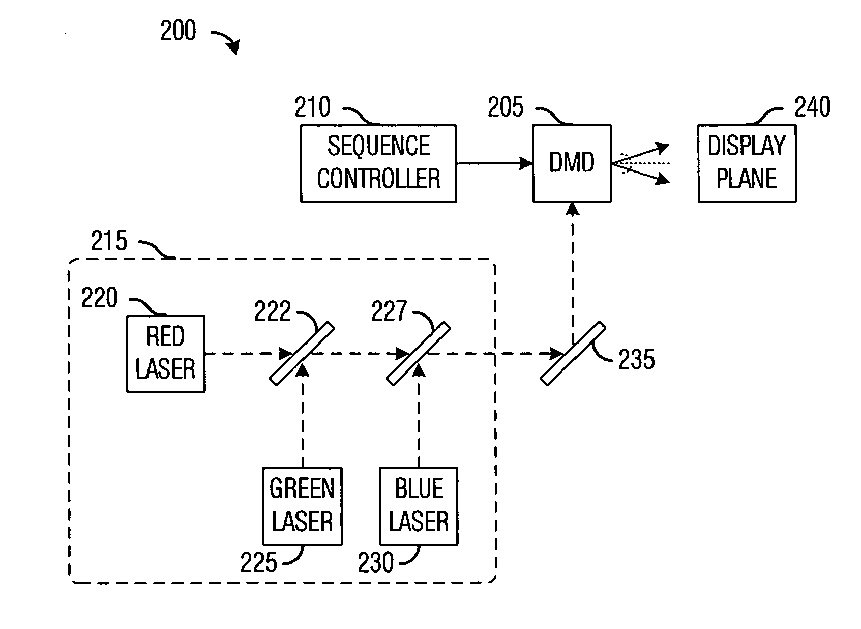
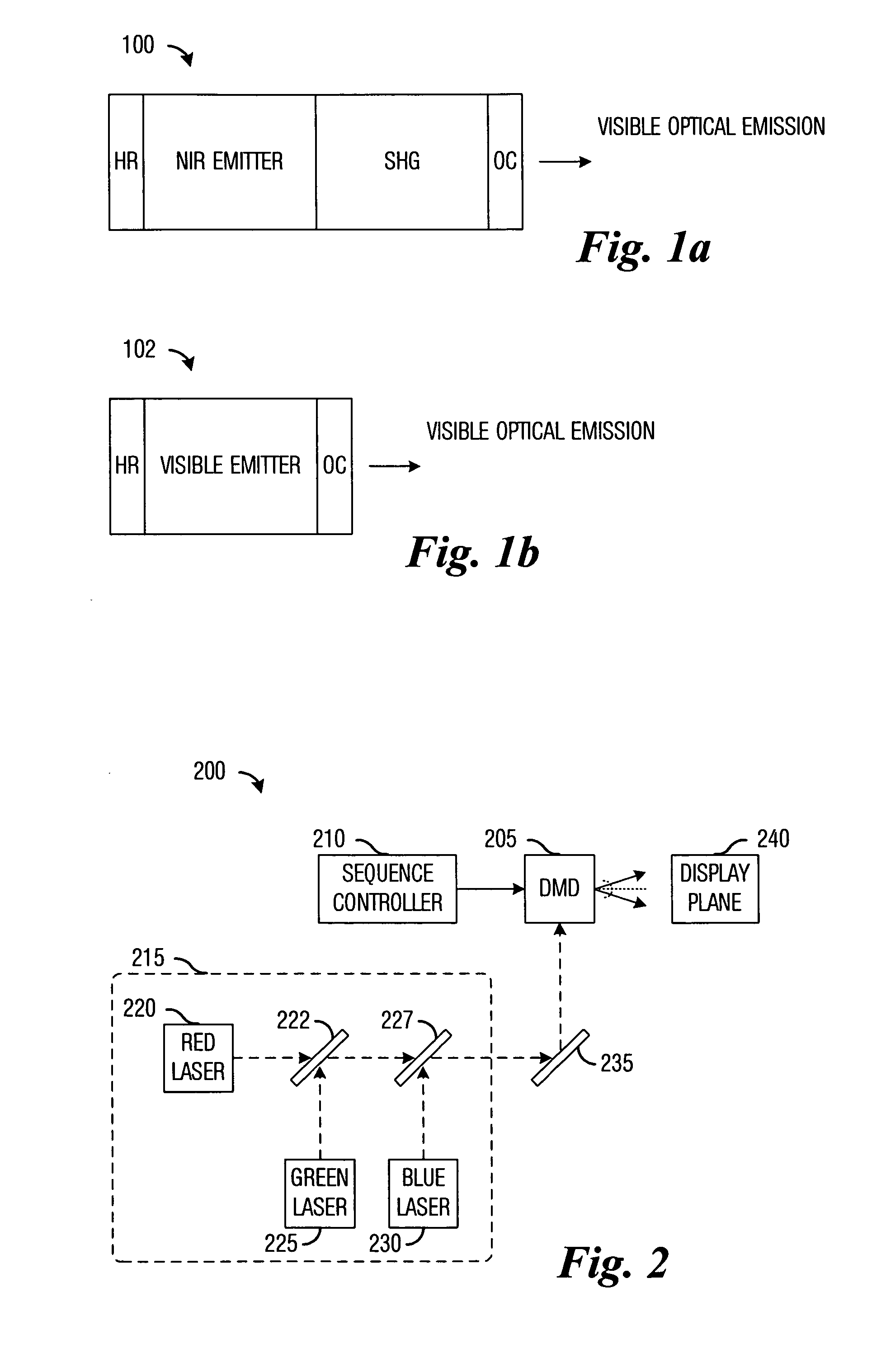
[0024]The present invention will be described with respect to preferred embodiments in a specific context, namely a solid-state light source utilizing laser diodes and / or light emitting diodes being used as a light source for a display system, wherein the spatial light modulator is a digital micromirror device (DMD). The invention may also be applied, however, to other display systems, such as display systems utilizing deformable mirrors, transmissive liquid crystals, reflective liquid crystals, liquid crystal on silicon, and so forth. Furthermore, the present invention can a...


PUM


Abstract

System and method for using predictive pulse modulation in display applications. A preferred embodiment comprises sampling a light output of a light source, computing a usage history of the light source, and processing the samples of the light output in combination with the usage history to characterize the light source. The characterization of the light source can be used in conjunction with a desired light output to determine a current pulse waveform to provide to the light source to have the light source produce the desired light output. The characterization of the light source can occur during normal use of the display system or during manufacture or setup and configuration of the display system.

Description

TECHNICAL FIELD[0001]The present invention relates generally to a system and a method for display systems, and more particularly to a system and method for using predictive pulse modulation in display applications.BACKGROUND[0002]In one embodiment of a display system, such as one used for television or digital projector applications, a spatial light modulator is illuminated with a light source or light sources containing component red (R), green (G), and blue (B) (and potentially other) colors. Light from the light source or light sources is then reflected off or transmitted through a spatial light modulator and is imaged to a screen or other surface for viewing. When using light emitting diodes or lasers in such displays, each source produces light in a relatively narrow region of the visible spectrum. Hence at least three laser or light emitting diode sources representing red, green and blue regions of the visible spectrum typically are used to produce a color display. Because the...

Claims


Application Information

Patent Timeline
Patent Type & Authority Applications(United States)
IPC IPC(8): G09G3/34
CPCG09G3/3406G09G2360/145G09G2320/064
Inventor DUNCAN, WALTER M.REUTER, FRED JAYRANCURET, PAUL L.
Owner TEXAS INSTR INC
Learn More