Adjustable quantitative injection pump

A quantitative injection and adjustable technology, applied in the field of syringe pumps, can solve the problems of injection and sampling pipeline pollution, troublesome control, high cost, etc., and achieve the effects of stable and reliable operation, simple control, and simple structure

Active Publication Date: 2012-06-27
JIANGNAN UNIV
View PDF5 Cites 6 Cited by
  • Summary
  • Abstract
  • Description
  • Claims
  • Application Information

AI Technical Summary

Problems solved by technology

[0003] The micro syringe pump mainly realizes liquid suction and discharge through the diaphragm and plunger, but the displacement of the pump is fixed, and it is impossible to change the pump volume on one pump. If you want to change the pump volume, you need to replace it with a new pump. , and the cost is high, it is difficult to meet the needs of use in some occasions that require multiple injections without interfering with each other
[0004] Most industrial syringe pumps use motor components and the propulsion mechanism connected with the syringe to work through gear transmission. Due to the complex structure, the injection pipeline is easy to cause pollution and is difficult to clean. If the injection system sucks Air is introduced into the bubble residual tube, which is generally difficult to completely eliminate, resulting in inaccurate sample injection, large volume, troublesome control, etc.
[0005] The peristaltic pump achieves pumping liquid by alternately squeezing and releasing the elastic delivery hose of the pump. Since the hose is constantly squeezed, the service life of the hose is relatively short, and the degree of compression of the hose will cause further damage. The change of sample volume makes the sampling accuracy of peristaltic pump not as good as that of syringe pump

Method used


Image

  • Adjustable quantitative injection pump
  • Adjustable quantitative injection pump
  • Adjustable quantitative injection pump

Examples


Embodiment Construction

[0018] The specific embodiments of the present invention will be further described below in conjunction with the accompanying drawings.

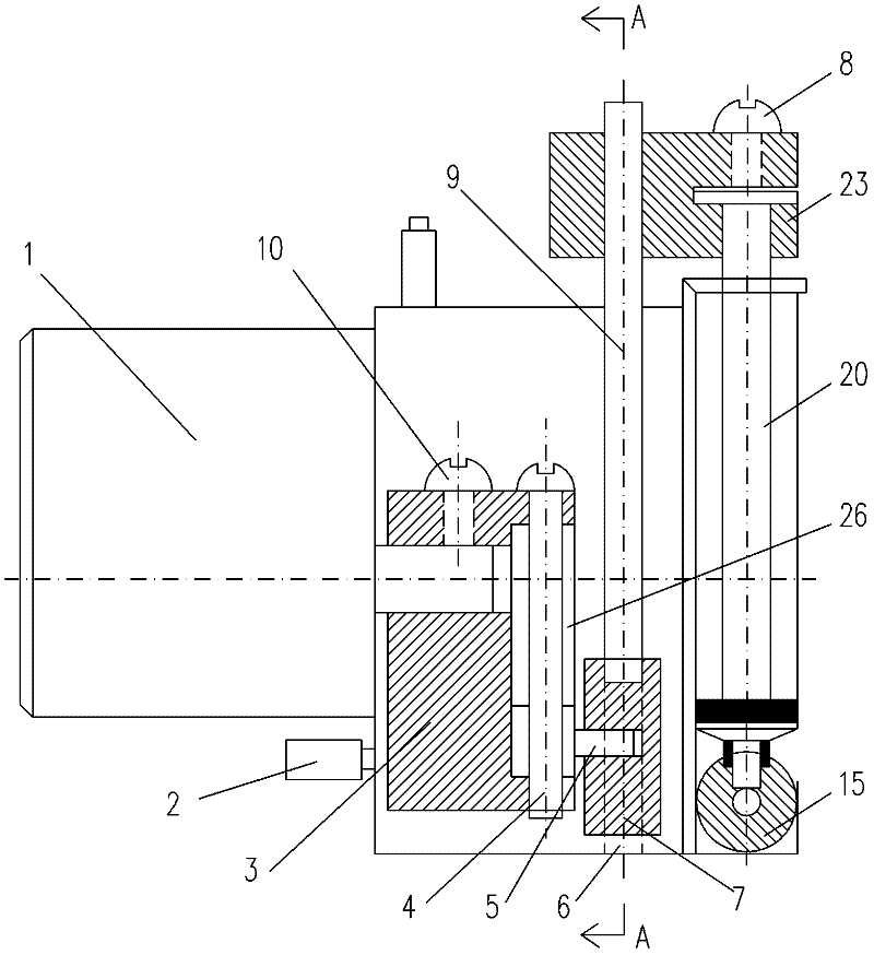
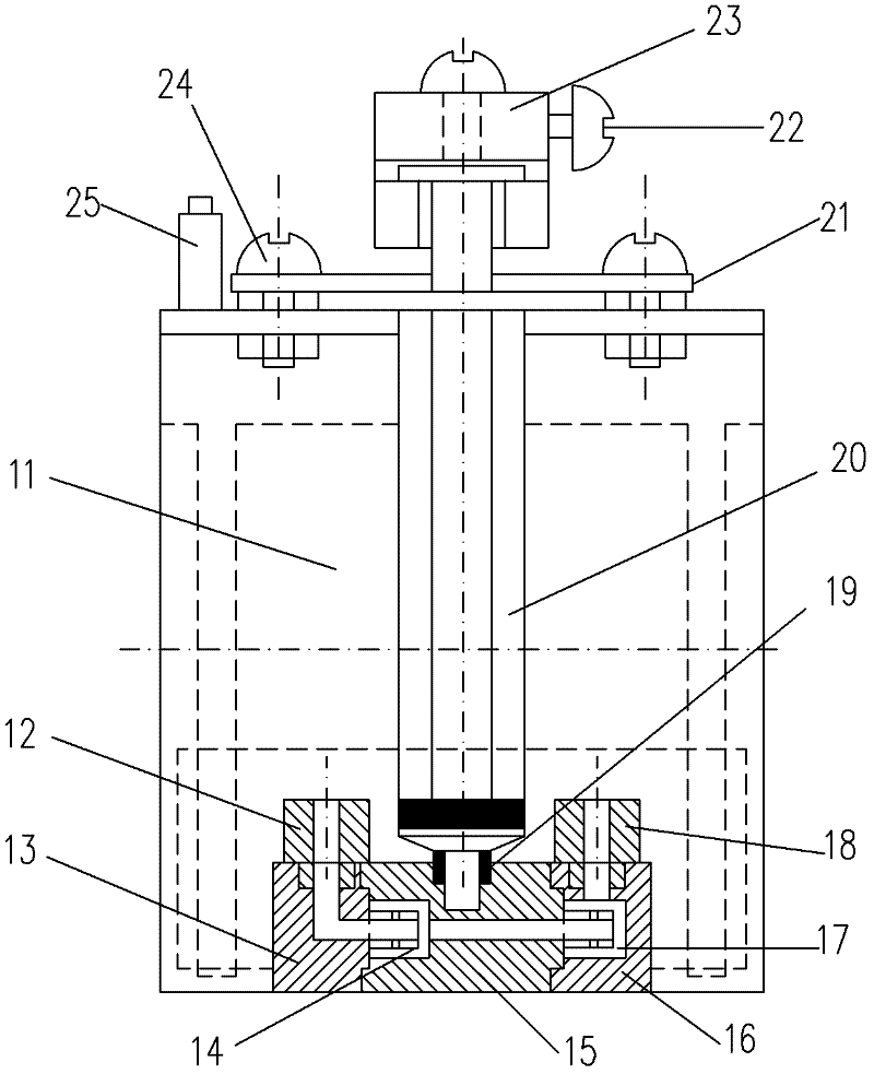
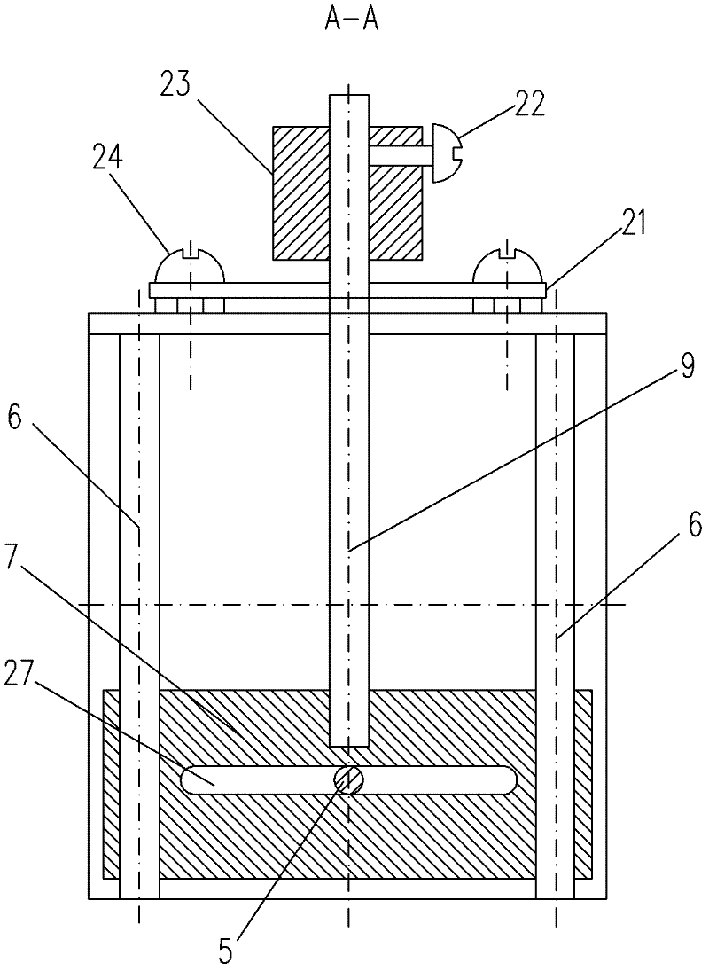
[0019] Figure 1~Figure 4 Including geared motor 1, micro switch 2, rotating block 3, adjusting screw 4, slider transmission pin 5, slider guide rod 6, slider 7, syringe push rod fixing screw 8, transmission rod 9, rotation block fixing Screw 10, pump body 11, suction port 12, suction valve 13, suction valve film 14, discharge valve 15, discharge cavity 16, discharge valve film 17, discharge port 18, sealing ring 19, syringe 20, syringe pressure plate 21, linkage Block fixing screw 22, linkage block 23, pressure plate screw 24, manual switch 25, vertical groove 26, transverse groove 27 etc.

[0020] like Figure 1~Figure 3 As shown, the present invention is an adjustable quantitative injection pump, including a pump body 11, on which a reduction motor 1 is installed, and a rotation block 3 is fixed on the output shaft of the reduction moto...


PUM


Abstract

The invention relates to an adjustable quantitative injection pump. A speed reduction motor is arranged on a pump body. A rotating block is fixed on an output shaft of the speed reduction motor. An adjusting screw rod vertical to the output shaft of the speed reduction motor is arranged on the rotating block. A sliding block drive pin is arranged on the adjusting screw rod. The axis of the sliding block drive pin is deviated from the axis of the output shaft of the speed reduction motor. The sliding block drive pin is matched in a transverse groove of a sliding block in a sliding mode. The sliding block is matched on a vertical sliding block guide rod in a sliding mode. A vertical drive rod is fixed on the sliding block. The drive rod is connected with a push rod of a syringe through a linkage block. According to the invention, a transmission mechanism of the syringe is formed by the speed reduction motor, the rotating block, the sliding block drive pin, the sliding block and the drive rod and drives the push rod of the syringe to take the piston motion, wherein the sliding block drive pin is arranged on the adjusting screw rod and the eccentricity of the sliding block drive pin relative to the output shaft of the speed reduction motor can be regulated, so that the output of the syringe is regulated. The adjustable quantitative injection pump has simple structure and low cost, is stably and reliable to operate and is simple and convenient to control.

Description

technical field [0001] The invention relates to a syringe pump for sampling water samples in a water quality on-line automatic monitoring device, in particular to an adjustable quantitative syringe pump. Background technique [0002] In the existing water quality on-line automatic monitoring device, three types of water samples are mainly used for sampling water samples: micro-injection pumps, industrial injection pumps and peristaltic pumps. [0003] The micro syringe pump mainly realizes liquid suction and discharge through the diaphragm and plunger, but the displacement of the pump is fixed, and it is impossible to change the pump volume on one pump. If you want to change the pump volume, you need to replace it with a new pump. , and the cost is high, and it is difficult to meet the needs of use in some occasions that require multiple injections without interfering with each other. [0004] Most industrial syringe pumps use motor components and the propulsion mechanism c...

Claims


Application Information

Patent Timeline
IPC IPC(8): F04B13/00F04B49/00G01N1/14
Inventor 胡惠新杨慧中李影丁明军陈刚
Owner JIANGNAN UNIV
Why Eureka
Try Eureka