Integrated LED bulb

a led bulb and led light technology, applied in the direction of lighting and heating apparatus, lighting support devices, coupling device connections, etc., to achieve the effect of constant output voltage, constant optical output, and constant output voltag

Active Publication Date: 2008-01-17
SANTAS BEST
View PDF47 Cites 109 Cited by
  • Summary
  • Abstract
  • Description
  • Claims
  • Application Information

AI Technical Summary

Benefits of technology

[0004] An embodiment of the present invention may comprise: an integrated LED bulb that replaces C-type incandescent bulbs comprising: a lens; a printed circuit board comprising: conductor leads that are connected to electrical conductors that connect to an alternating current electrical source; a full wave rectifier that rectifies the alternating current electrical source to generate a full wave rectified output signal; an integrating capacitor that integrates the full wave rectified output signal to generate an integrated direct current signal; a zener diode that controls the voltage level of the integrated direct current signal to produce a substantially constant output voltage; at least one light emitting diode disposed in the lens that is connected in parallel with the zener diode, and that generates a substantially constant optical output in response to the substantially constant output voltage produced by the zener diode, the light emitting diode having pin leads that are soldered directly to the printed circuit board; a base that is over-molded around the printed circuit board, the conductors, and the leads that are connected to the electrical conductors and the pin leads that are soldered to the printed circuit boards to form a secure, stable base that protects the printed circuit board, and which has a standard format for C-type bulbs, so that the base fits into standard C-type bulb sockets that are attached to the alternating current electrical source.
[0005] Another embodiment of the present invention may comprise: a method of making an LED bulb that replaces C-type incandescent bulbs comprising: providing a lens; providing at least one LED; connecting the at least one LED in parallel with a zener diode disposed on a printed circuit board using LED pin leads that are soldered to connectors on the printed circuit board; connecting the zener diode in parallel with an integrating capacitor disposed on the printed circuit board so that a substantially constant output voltage is produced that is applied to the at least one LED to provide a substantially constant optical output; connecting the integrating capacitor in parallel with a full wave rectifier disposed on the printed circuit board so that a source of alternating current applied to the full wave rectifier is integrated by the integrating capacitor; connecting electrical conductors to the full wave rectifier; and molding a base around the printed circuit board, the LED pin leads, the conductors and the conductor leads to form a secure, stable base that has a standard format for C-type bulbs, so that the base fits into standard C-type bulb sockets that are attached to the source of alternating current.

Problems solved by technology

Since the time that light bulbs were invented in 1879, light bulbs have had a significant effect on human activity by providing illumination in areas and at times that would not otherwise allow such activities.

Method used


Image

  • Integrated LED bulb
  • Integrated LED bulb
  • Integrated LED bulb

Examples


Embodiment Construction

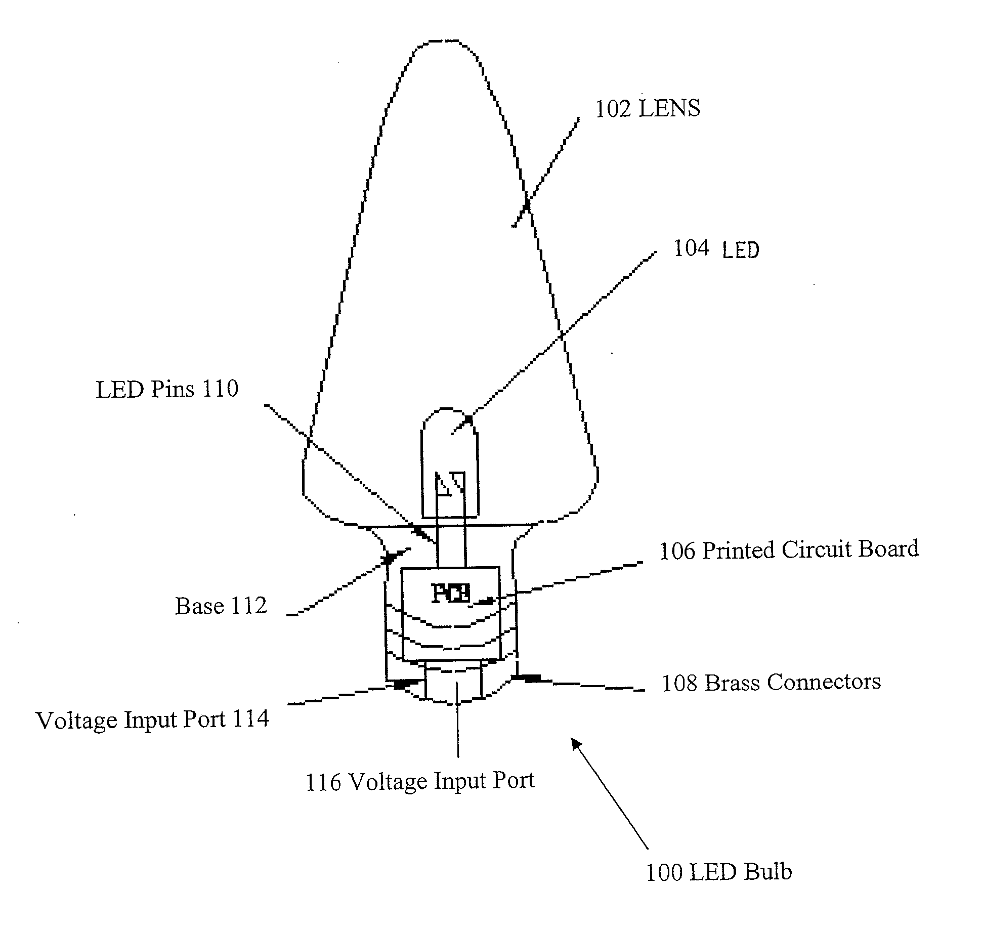
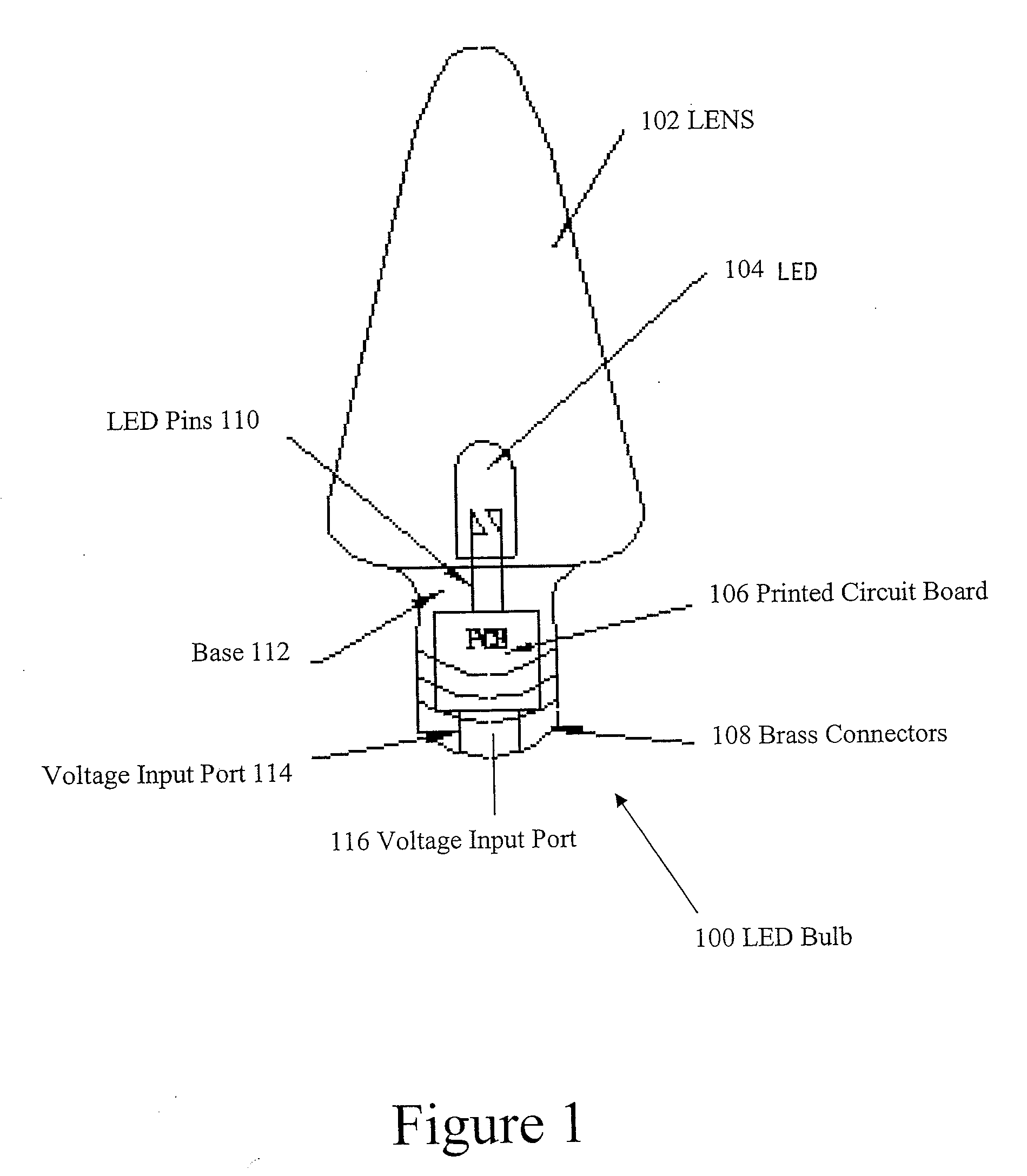
[0009]FIG. 1 discloses an integrated LED bulb 100. As shown in FIG. 1, the LED bulb 100 may be a C7 type bulb, or a C9 type bulb, such as those used as screw-in Christmas tree light bulbs. The C7 type and C9 type bulbs can also have bayonet type connectors, although the screw-in type is a more common type of connector. The integrated LED bulb 100 includes a lens 102 that is connected to a base 112. Connection of the lens 102 to the base 112 can be effectuated in the manner disclosed in U.S. Provisional Patent Application 60 / 949,804, filed Jul. 13, 2007, entitled “Water Tight LED Lamp,” which is specifically incorporated herein by reference for all that it discloses and teaches. In other words, the lens 102 may have a neck portion that is inserted into a socket in the base 112. Alternatively, base 112 and lens 102 may be attached by using thermal bonding, sonic bonding, or solvent bonding, a friction interference fit, use of an adhesive or threaded screws that allow the lens 102 to b...


PUM


Abstract

Disclosed is an integrated LED bulb that utilizes LEDs and can be used as a standard replacement bulb for incandescent lights that operate on standard household current. One or more LEDs are disposed in a lens 102 that is capable of high optical transmission efficiencies. A base portion encapsulates a printed circuit board and connectors, as well as the LED pin leads to hold the package in a secure mounting. The lens can be molded directly to the base or can be removable. The base can be formed to fit standard threaded sockets or bayonet sockets.

Description

CROSS REFERENCE TO RELATED APPLICATIONS [0001] This application is a continuation of U.S. patent application Ser. No. 11 / 189,066 entitled “C7, C9 LED Bulb and Embedded PCB Circuit Board,” by Jing Jing Yu, filed Jul. 26, 2005, and is based upon U.S. Provisional Patent Application Ser. No. 60 / 949,804, entitled “Watertight LED Lamp,” by Jing Jing Yu, filed Jul. 13, 2007. The entire contents of the above mentioned applications are hereby specifically incorporated herein by reference for all they disclose and teach.BACKGROUND OF THE INVENTION [0002] Lighting is an important part of everyday life. Since the time that light bulbs were invented in 1879, light bulbs have had a significant effect on human activity by providing illumination in areas and at times that would not otherwise allow such activities. One of the goals of developing lighting technologies is to meet desired illumination requirements for various activities in various venues, such as homes, offices, restaurants, etc., and ...

Claims


Application Information

Patent Timeline
Patent Type & Authority Applications(United States)
IPC IPC(8): F21V5/00
CPCF21Y2101/02H05B33/0803H05B33/0809F21V3/02F21K9/135F21W2121/00Y10S362/80Y02B20/348F21K9/232F21Y2115/10Y02B20/30H05B45/34
Inventor YU, JING JING
Owner SANTAS BEST
Why Eureka
Try Eureka