Data transfer device of serializer/deserializer system

a technology of serializers and deserializers, applied in the field of data transfer devices of serializers/deserializers, can solve the problems of affecting the transmission margin and distorted signal waveforms, and achieve the effect of expanding the transmission margin of high-speed and long-distance signals

Inactive Publication Date: 2008-01-17
HITACHI LTD
View PDF14 Cites 17 Cited by
  • Summary
  • Abstract
  • Description
  • Claims
  • Application Information

AI Technical Summary

Benefits of technology

[0017]Since the optimum set values for the offsets of the differential amplifier and the transmission system and the pre-emphasis amount of the output pre-emphasis circuit can be selected for each channel, the high-speed and long-distance signal transmission margin can be expanded. Further, even in an asynchronous signal transmission system, the offsets of the differential amplifier and the differential signal can be also corrected and the optimum set value for the pre-emphasis amount of the output pre-emphasis circuit can be also detected.

Problems solved by technology

As a result of investigation by the Inventor in order to apply the serializer / deserializer system in the inter-LSI signal transmission, it becomes clear that there are the following problems.
Since effective input amplitude gets smaller due to the offsets, there arises a problem that the transmission margin is influenced greatly.
Moreover, In high-speed and long-distance signal transmission, transmission data is influenced by data existing before and after the transmission data due to the intersymbol interference (ISI), so that the signal waveform thereof is distorted remarkably.

Method used


Image

  • Data transfer device of serializer/deserializer system
  • Data transfer device of serializer/deserializer system
  • Data transfer device of serializer/deserializer system

Examples


Embodiment Construction

[0028]Embodiments of the present invention are now described with reference to the accompanying drawings.

A. Whole Configuration of System

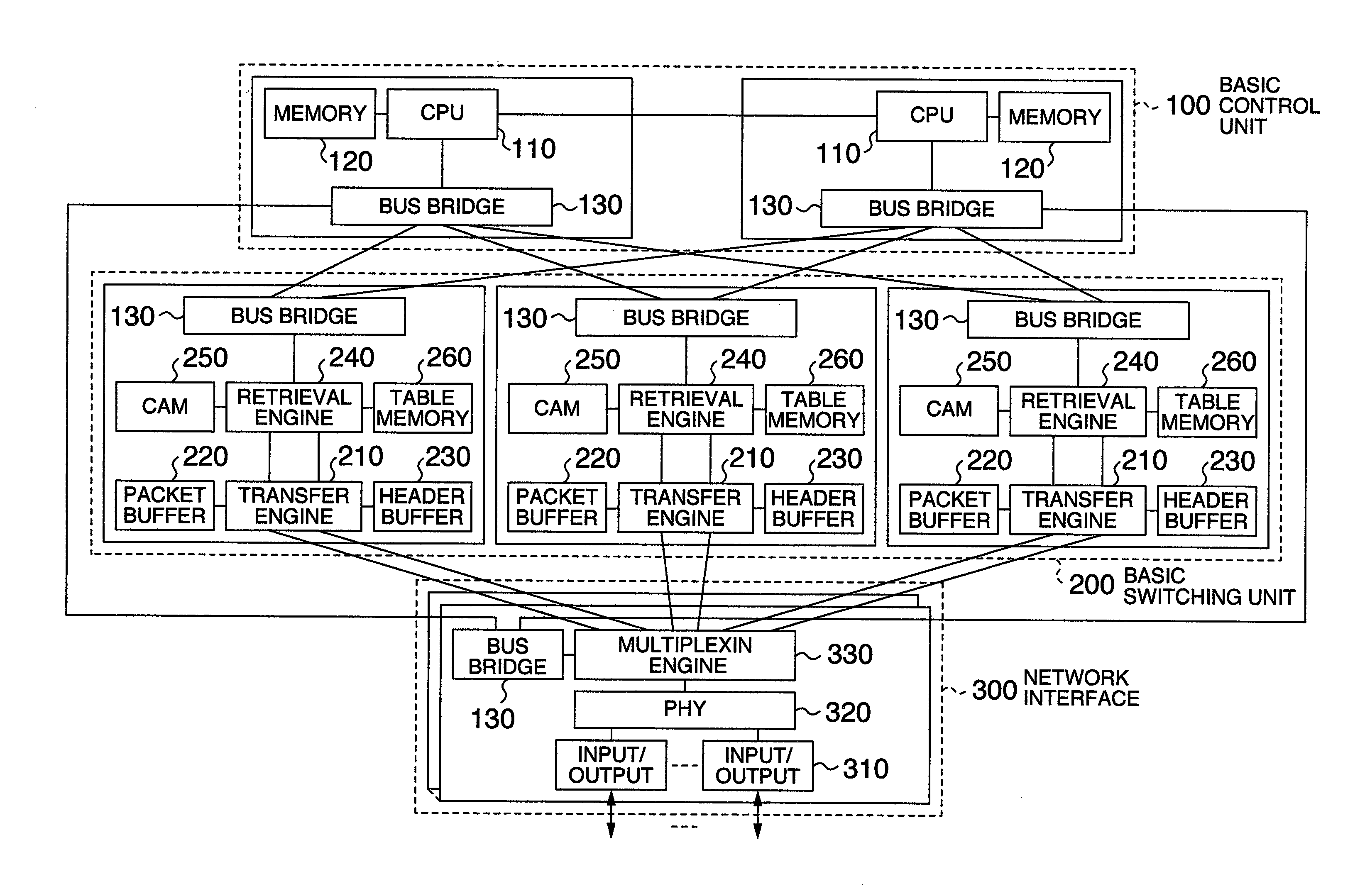
[0029]FIG. 1 is a block diagram schematically illustrating an example of a network apparatus to which the present invention is applied. The system includes three main units containing a basic control unit 100, a basic switching unit 200 and a network interface 300. In FIG. 1, the basic control unit 100 is configured to a redundant system of 1+1 and the basic switching unit 200 is configured to a redundant system of 2+1, by way of example. The basic control unit 100 performs management of the apparatus, control of interfaces between units and the like and includes a central processing unit (CPU) 110, a main memory 120 and a bus bridge 130. The bus bridge 130 is provided in each unit and the access of each unit to the CPU 110 is made through the bus bridge 130. The basic switching unit 200 performs transfer function, retrieval function and filtering ...


PUM


Abstract

In a data transfer device which cancels an offset of a differential amplifier for amplifying a received signal and an offset caused by characteristics of a differential transmission line and selects optimum conditions such as pre-emphasis amount of an output pre-emphasis circuit, a first chip (transmission side LSI=transfer engine 210) and a second chip (reception side LSI=multiplexing engine 330) are connected to each other through differential transmission line 430 and a SerDes (serializer) 401 and a SerDes (deserializer) 402 are used to make signal transmission, so that optimum setting conditions of an offset amount of an offset cancellation circuit included in an input buffer amplifier and a pre-emphasis amount of pre-emphasis circuit included in an output buffer are decided in training using a training PRBS generator 560 and a training PRBS comparator 570.

Description

CLAIM OF PRIORITY[0001]The present application claims priority from Japanese application JP-2006-193548 filed on Jul. 14, 2006, the content of which is hereby incorporated by reference into this application.BACKGROUND OF THE INVENTION[0002]The present invention relates to a technique which can be effectively applied to cancellation of offsets of an input differential signal and a differential amplifier and an equalization amount of an output pre-emphasis circuit in an inter-LSI (large-scale integrated circuit) data transfer system of a network apparatus and, for example, a technique which can be effectively utilized in the network apparatus and LSIs used in the network apparatus.[0003]Heretofore, in the inter-LSI data transfer system, the technique disclosed in JP-A-2005-20119 and JP-A-8-116340 is used to cancel a DC offset.[0004]However, recently, a serializer / deserializer system in which bus is serialized and signal is transmitted at high speed is being often used in parts requiri...

Claims


Application Information

Patent Timeline
Patent Type & Authority Applications(United States)
IPC IPC(8): H04L12/28
CPCH04L25/0288H04L25/0274
Inventor MUTO, TAKASHIFUJIMURA, YASUHIROHIGETA, KEIICHIBABA, JUNJIMURANAKA, TAKAYUKIKIMURA, ISAO
Owner HITACHI LTD
Why Eureka
Try Eureka