Optical fiber, transmission system, and wavelength division multiplexing system

a transmission system and optical fiber technology, applied in the field of optical fiber, to achieve the effect of suppressing the occurrence of sbs

Inactive Publication Date: 2008-01-17
THE FUJIKURA CABLE WORKS LTD
View PDF5 Cites 40 Cited by
  • Summary
  • Abstract
  • Description
  • Claims
  • Application Information

AI Technical Summary

Benefits of technology

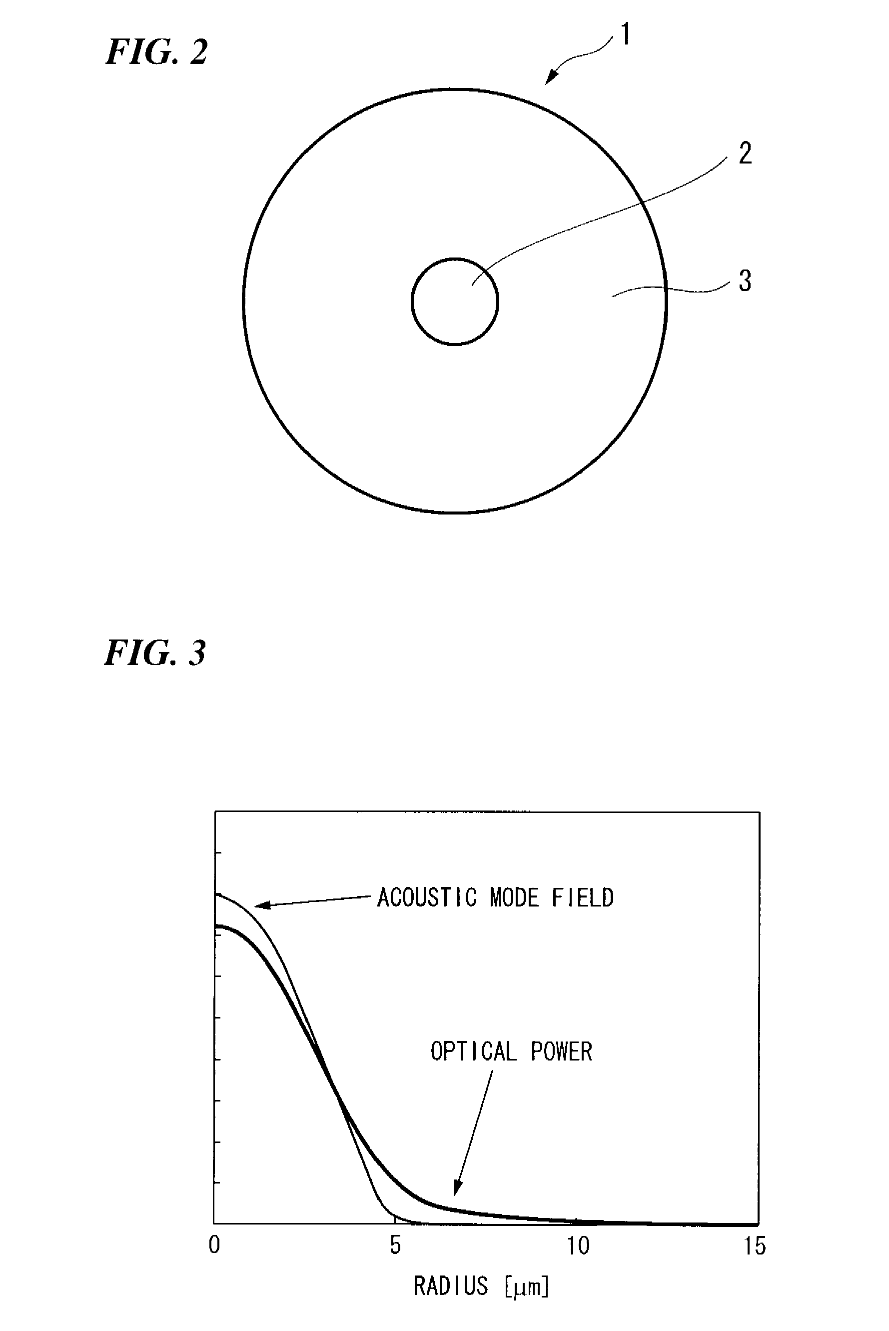
[0021] In the optical fiber of the present invention, by reducing an overlap between an acoustic field distribution and a light power distribution of the optical fiber, occurrence of simulated Brillouin scattering can be reduced as compared to an optical fiber with equivalent optical characteristics.
[0022] In the optical fiber of the present invention, by expanding the acoustic field distribution of the optical fiber to be larger than the light power distribution thereof, an overlap between the acoustic field distribution and the light power distribution can be reduced.
[0023] Alternatively, by making the acoustic field distribution of the optical fiber smaller than the light power distribution thereof, an overlap between the acoustic field distribution and the light power distribution can be reduced.
[0036] The present invention can provide an optical fiber that suppresses the occurrence of SBS to allow transmission of higher power signals, and a transmission system and a wavelength division multiplexing system that enable multi-branched, long-distance transmission by use of the optical fiber.

Problems solved by technology

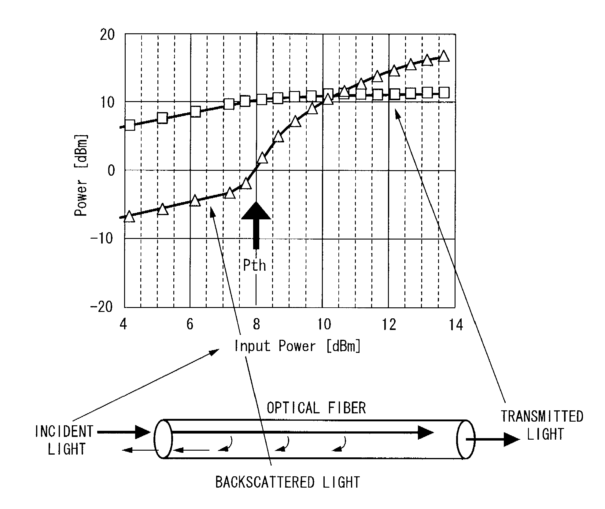
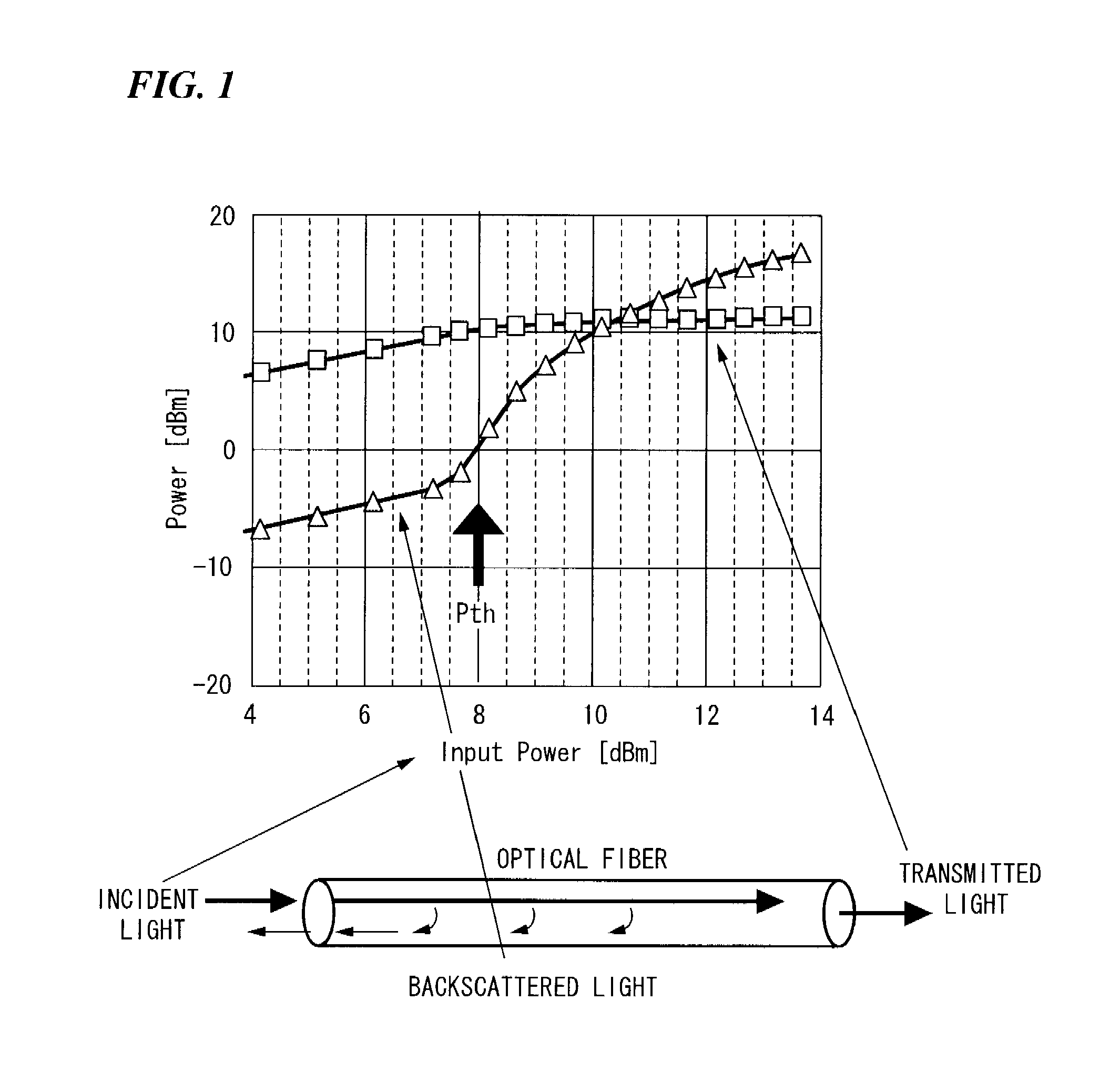
This phenomenon sometimes puts restrictions on signal light power in the input portion, thus posing a problem (for example, see Non-Patent Document 1).

Method used


Image

  • Optical fiber, transmission system, and wavelength division multiplexing system
  • Optical fiber, transmission system, and wavelength division multiplexing system
  • Optical fiber, transmission system, and wavelength division multiplexing system

Examples


first embodiment

[0131]FIG. 9 shows the refractive index profile of a first exemplary embodiment. An optical fiber of the first embodiment has a profile in which the refractive index is maximum near the center and decreases with a substantially fixed gradient with respect to the radius. Optical characteristics of the optical fiber with the refractive index shown in FIG. 9 will be shown below. FIG. 10 shows the distributions of the optical power and the acoustic mode of this embodiment. [0132] The fiber cut-off wavelength is 1.25 μm. [0133] The cable cut-off wavelength is 1.20 μm. [0134] The mode field diameter (Petermann II) is 9.46 μm at a wavelength of 1310 nm and 10.86 μm at a wavelength of 1550 nm. [0135] The zero-dispersion wavelength is 1330.5 nm. [0136] The wavelength dispersion value is −1.90 ps / nm / km at a wavelength of 1310 nm and 16.27 ps / nm / km at a wavelength of 1550 nm. [0137] The bending loss at a bending diameter of 20 mm is 2.6 dB / m at a wavelength of 1310 nm and 39.5 dB / m at a wavele...

second embodiment

[0141]FIG. 12 shows the refractive index profile of a second exemplary embodiment. The optical fiber of the second embodiment has a refractive index profile of a core with two layers. Optical characteristics of the optical fiber with the refractive index shown in FIG. 12 will be shown below. FIG. 13 shows the distributions of the optical power and the acoustic mode of this embodiment. [0142] The fiber cut-off wavelength is 1.29 μm. [0143] The cable cut-off wavelength is 1.22 μm. [0144] The mode field diameter (Petermann II) is 9.27 μm at a wavelength of 1310 nm and 10.53 μm at a wavelength of 1550 nm. [0145] The zero-dispersion wavelength is 1326.3 nm. [0146] The wavelength dispersion value is −1.55 ps / nm / km at a wavelength of 1310 nm and 16.77 ps / nm / km at a wavelength of 1550 nm. [0147] The bending loss at a bending diameter of 20 mm is 0.5 dB / m at a wavelength of 1310 nm and 12.8 dB / m at a wavelength of 1550 nm. [0148] The optical MFD is 6.59 μm at a wavelength of 1550 nm. [0149] ...

third embodiment

[0151]FIG. 15 shows the refractive index profile of a third exemplary embodiment. The optical fiber of the third embodiment has a refractive index profile of a core with two layers. Optical characteristics of the optical fiber with the refractive index shown in FIG. 15 will be shown below. FIG. 16 shows the distributions of the optical power and the acoustic mode of this embodiment. [0152] The fiber cut-off wavelength is 1.26 μm. [0153] The cable cut-off wavelength is 1.20 μm. [0154] The mode field diameter (Petermann II) is 9.31 μm at a wavelength of 1310 nm and 10.70 μm at a wavelength of 1550 nm. [0155] The zero-dispersion wavelength is 1335.3 nm. [0156] The wavelength dispersion value is −2.43 ps / nm / km at a wavelength of 1310 nm and 16.14 ps / nm / km at a wavelength of 1550 nm. [0157] The bending loss at a bending diameter of 20 mm is 2.1 dB / m at a wavelength of 1310 nm and 34.8 dB / m at a wavelength of 1550 nm. [0158] The optical MFD is 6.83 μm at a wavelength of 1550 nm. [0159] Th...


PUM


Abstract

An optical fiber has a first mode field diameter in a dominant mode of an acoustic mode generated in the optical fiber different from a second mode field diameter in a light intensity distribution of the optical fiber. Furthermore, a transmission system is configured to perform an analog signal transmission, a baseband transmission, or an optical SCM transmission by use of the optical fiber.

Description

CROSS-REFERENCE TO RELATED PATENT APPLICATIONS [0001] This Application claims priority from PCT Application No. PCT / JP2005 / 020368, filed Nov. 7, 2005, and from Japanese Patent Application No. 2004-321912 filed on Nov. 5, 2004, Japanese Patent Application No. 2005-77008 filed on Mar. 17, 2005, and Japanese Patent Application No. 2005-197639 filed on Jul. 6, 2005, the contents of which are incorporated herein by reference.BACKGROUND OF THE INVENTION [0002] 1. Field of the Invention [0003] Apparatuses consistent with the present invention relates to an optical fiber that suppresses the occurrence of Simulated Brillouin Scattering (hereinafter referred to as SBS) to allow transmission of higher-power signals. [0004] 2. Description of the Related Art [0005] Nowadays, service, hereinafter referred to as FTTH, is available in which optical fibers are extended to individual homes to be used for exchange of various information. [0006] As one form of FTTH that transmits various information, t...

Claims


Application Information

Patent Timeline
Patent Type & Authority Applications(United States)
IPC IPC(8): G02B6/036H04B10/2537
CPCG02B6/02004H04J14/0252G02B6/02266G02B6/0281G02B6/0286G02B6/03605G02B6/03644G02B6/03666G02B6/03688H04B10/2537H04J14/02H04J14/0226H04J14/0282H04J14/0232H04J14/0247G02B6/02009G02B6/02G02B6/036
Inventor MATSUO, SHOICHIROTANIGAWA, SHOJIUCHIYAMA, KEISUKEHIMENO, KUNIHARU
Owner THE FUJIKURA CABLE WORKS LTD
Why Eureka
Try Eureka