Transceiver architecture and method for wireless base-stations

a wireless base station and transceiver technology, applied in the direction of sustainable buildings, high-level techniques, wireless communication, etc., can solve the problems of large loss of transmit power in coaxial cables, loss of efficiency in coaxial cables, and inability to meet the needs of wireless base stations

Inactive Publication Date: 2008-01-17
ANDREW LLC
View PDF63 Cites 137 Cited by
  • Summary
  • Abstract
  • Description
  • Claims
  • Application Information

AI Technical Summary

Problems solved by technology

However, as is well known in the art, a large amount of the transmit power is lost in the coaxial cables 24 because of cable impedance and transmission loss.
However, amplifiers positioned at the top of a tower along with the antennas to form what is often referred to as an “active antenna” arrangement are not

Method used


Image

  • Transceiver architecture and method for wireless base-stations
  • Transceiver architecture and method for wireless base-stations
  • Transceiver architecture and method for wireless base-stations

Examples


Embodiment Construction

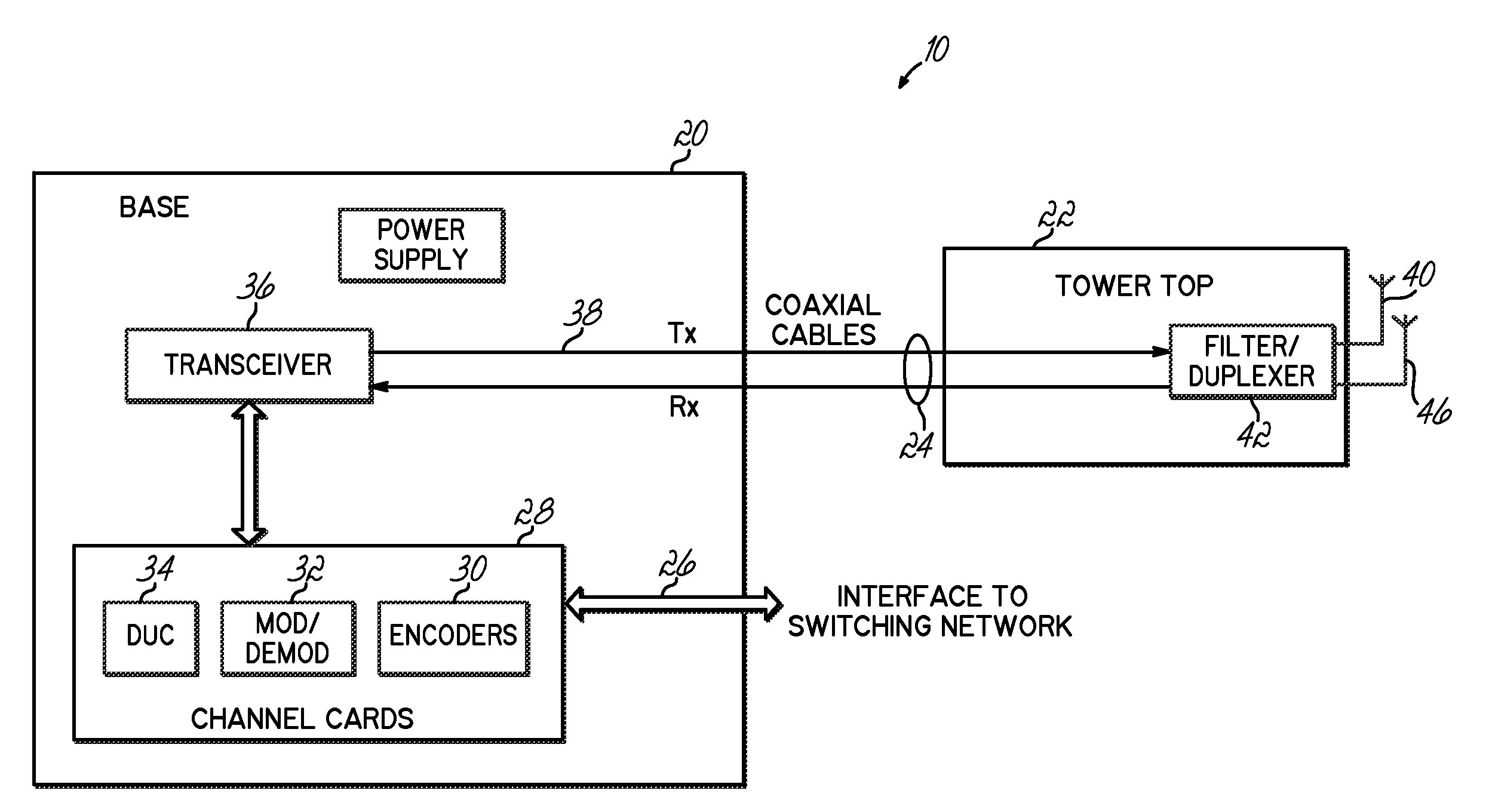
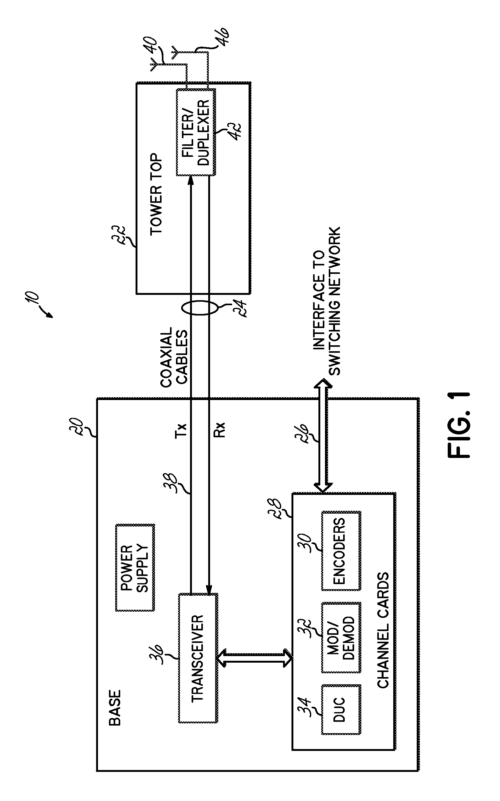
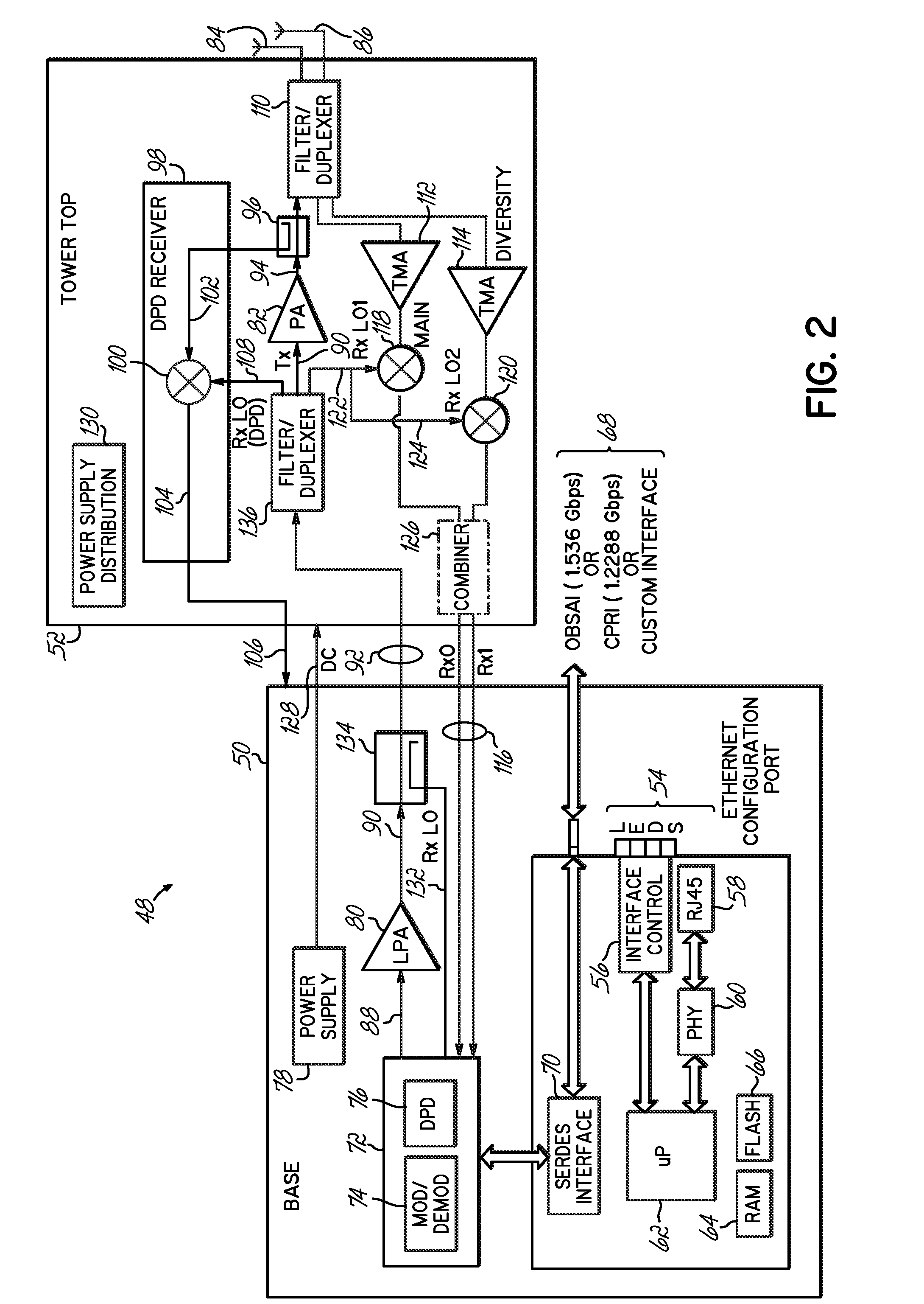
[0016]FIG. 2 illustrates one embodiment of a system 48 for wireless communications in accordance with the principles of the present invention. As utilized in FIG. 1, the various components illustrated in the block diagram might be utilized in an environment commonly considered a base-station, although the present invention has applicability other than with a conventional base-station. Referring to FIG. 2, the various components of the system are indicated as located in or at a base 50 or at a tower top 52. As noted, base 50 generally refers to the base of a tower structure or other support structure on which transmit and receive antennas are mounted. Base 50 generally indicates a position of the various components rather than a particular form for the base. In one example, the base might be a traditional housing or shed which is utilized to contain, cover and cool the components, to keep them in an environment with a generally consistent temperature and generally unexposed to the el...


PUM


Abstract

A system for wireless communications includes a tower structure supporting at least one transmit antenna at an elevated position on the tower structure and base electronics positioned proximate a base of the tower structure. The base electronics are coupled with the transmit antenna and include an initial stage amplifier for amplifying an input signal to provide a low power transmission signal that is provided to the transmit antenna at the elevated position.
A final stage amplifier is positioned proximate the transmit antenna. The final stage amplifier is a high efficiency amplifier for efficiently amplifying the low power transmission signal from the base electronics to provide a high power transmission signal to be transmitted from the transmit antenna.

Description

FIELD OF THE INVENTION[0001]The present invention is directed to wireless transceiver systems for use in wireless communication systems, and specifically is directed to a transceiver architecture for a wireless base-station that has applicability in wireless networks, such as cellular networks, and WiMAX networks.BACKGROUND OF THE INVENTION[0002]Wireless communication networks are utilized for a variety of different applications, including the transfer of voice and data information between the users of such networks. For example, advanced wireless networks are utilized for wireless communication applications, such as cellular systems, including cellular telephone systems, and other wireless networks, such as the more recent WiMAX networks.[0003]In general, a wireless communication network utilizes a fixed network that may include or be functionally coupled with existing communications networks, such as the established Public Switched Telephone Network (PSTN) or other networks having...

Claims


Application Information

Patent Timeline
IPC IPC(8): H04B7/185H04B7/14H04M1/00
CPCH03F1/3247H03F3/24Y02B60/50H03F2200/411H04W88/08Y02D30/70
Inventor LIPOWSKI, JOSEPH T.CHANDRASEKARAN, RAJIV
Owner ANDREW LLC
Why Eureka
Try Eureka