
Shapeable for steerable guide sheaths and methods for making and using them

a guide sheath and shape technology, applied in the direction of transvascular endocardial electrodes, ear treatment, surgery, etc., can solve the problems of embolic material dislocation, catheters or other instruments may dissect or otherwise damage the walls of a vessel instruments may be difficult to reach, so as to facilitate positioning within a targeted side branch or other body lumen, facilitate navigation, and facilitate the effect of positioning

Inactive Publication Date: 2008-01-17
MEDTRONIC INC
View PDF99 Cites 121 Cited by
  • Summary
  • Abstract
  • Description
  • Claims
  • Application Information

AI Technical Summary

Benefits of technology

[0011] In one embodiment, the rigidity of the stylet may be substantially greater than a distal tip of the elongate member such that the distal tip complies at least partially with a shape of the stylet when the stylet is advanced and / or positioned within the distal tip. For example, the stylet may have a predetermined shape set into the stylet before use, or the stylet may be malleable such that the stylet may be shaped by a user, e.g., to a desired curvature and / or angle that may facilitate navigation and / or cannulation of a target body lumen. Optionally, the distal tip of the elongate member may be pre-shaped to a predetermined curvature and / or angle, non-shaped, or “floppy,” e.g., to facilitate accessing a target body lumen.
[0013] In a first embodiment, the stylet may have a distal shape-set tip and a substantially flexible distal tip may be provided on the elongate member that conforms substantially to the angle of deflection of the stylet tip. In another embodiment, the elongate member may include a shape-set distal tip and the stylet may include a shape-set tip such advancement of the stylet changes the shape of the distal tip and withdrawal of the stylet may bias the distal tip back towards its initial shape-set. Optionally, the stylet may be integrated with a handle of the tubular member to facilitate advancing and / or advancing the stylet while performing a medical procedure. In a further embodiment, the stylet may be removable and / or rotatable relative to the elongate member. For example, the shape-set distal tip of the elongate member may be advanced within a body lumen with the shape-set stylet in one orientation, and the stylet may be rotated, advanced, retracted, and / or otherwise moved relative to the distal tip such that each of the shape-set combinations may produce different profiles that may be shaped and / or steerable to facilitate tracking and / or navigation within a body cavity or lumen.
[0015] In yet another embodiment, a catheter with a shape-set stylet may achieve various deflections and / or geometries from advancing and / or retracting the stylet for further accessing a coronary side-branch or tributary. For example, as the stylet's position is adjusted, the catheter may exhibit varying curvatures to facilitate navigation through vessels and side-branches. In one embodiment, the stylet may be held substantially stationary while the catheter is advanced, e.g., over the stylet, to facilitate positioning within a targeted side branch or other body lumen. If the distal tip is shaped, a side branch having an acute take-off angle may be easily cannulated using a combination of a shape-set distal tip and a shape-set stylet.

Problems solved by technology

There are many risks involved with advancing instruments through a patient's vasculature.
For example, a catheter or other instrument may dissect or otherwise damage a wall of a vessel or other body lumen, for example, as the instrument passes through narrow passages and / or tortuous anatomy, e.g., involving sharp bends.
Such instruments also risk dislodging embolic material or even perforating body lumens.
However, instrument(s) used to access the vessels, e.g., a guide sheath, lead, and the like, may have a relatively large cross-section and / or may have relatively blunt and / or stiff distal tips, making it difficult to advance such instruments as deeply as desired into such small vessels.

Method used


Image

  • Shapeable for steerable guide sheaths and methods for making and using them
  • Shapeable for steerable guide sheaths and methods for making and using them
  • Shapeable for steerable guide sheaths and methods for making and using them

Examples


Embodiment Construction

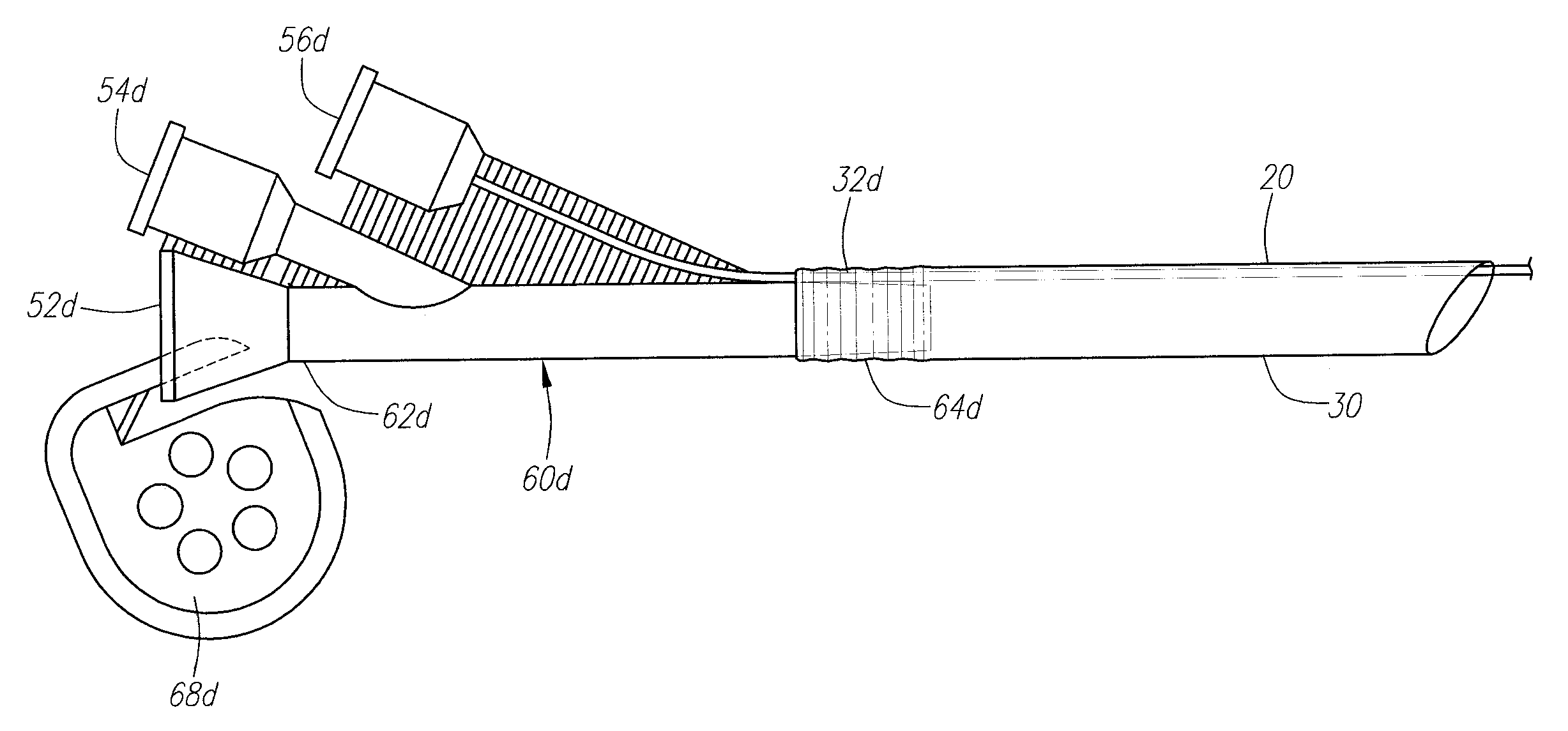
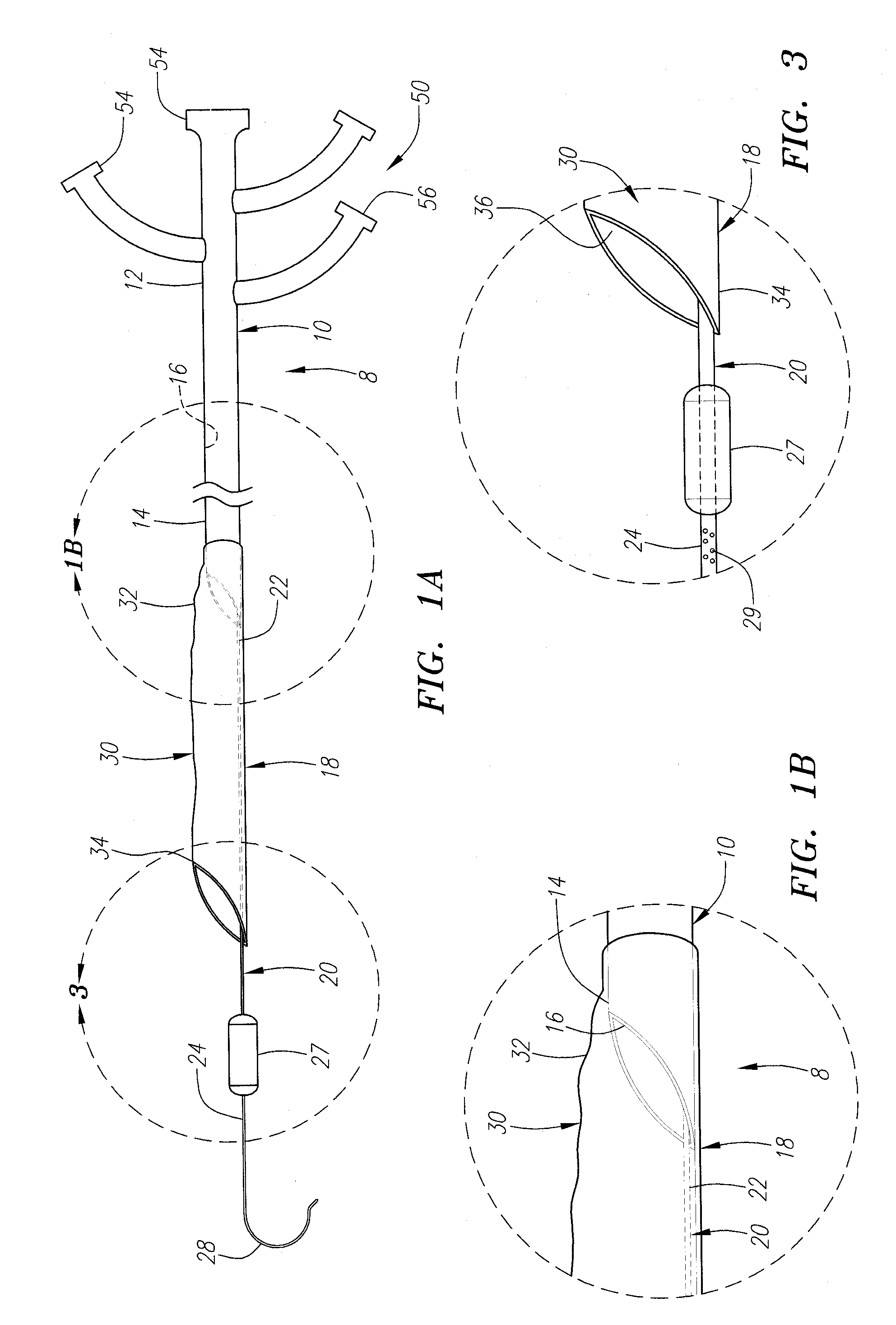
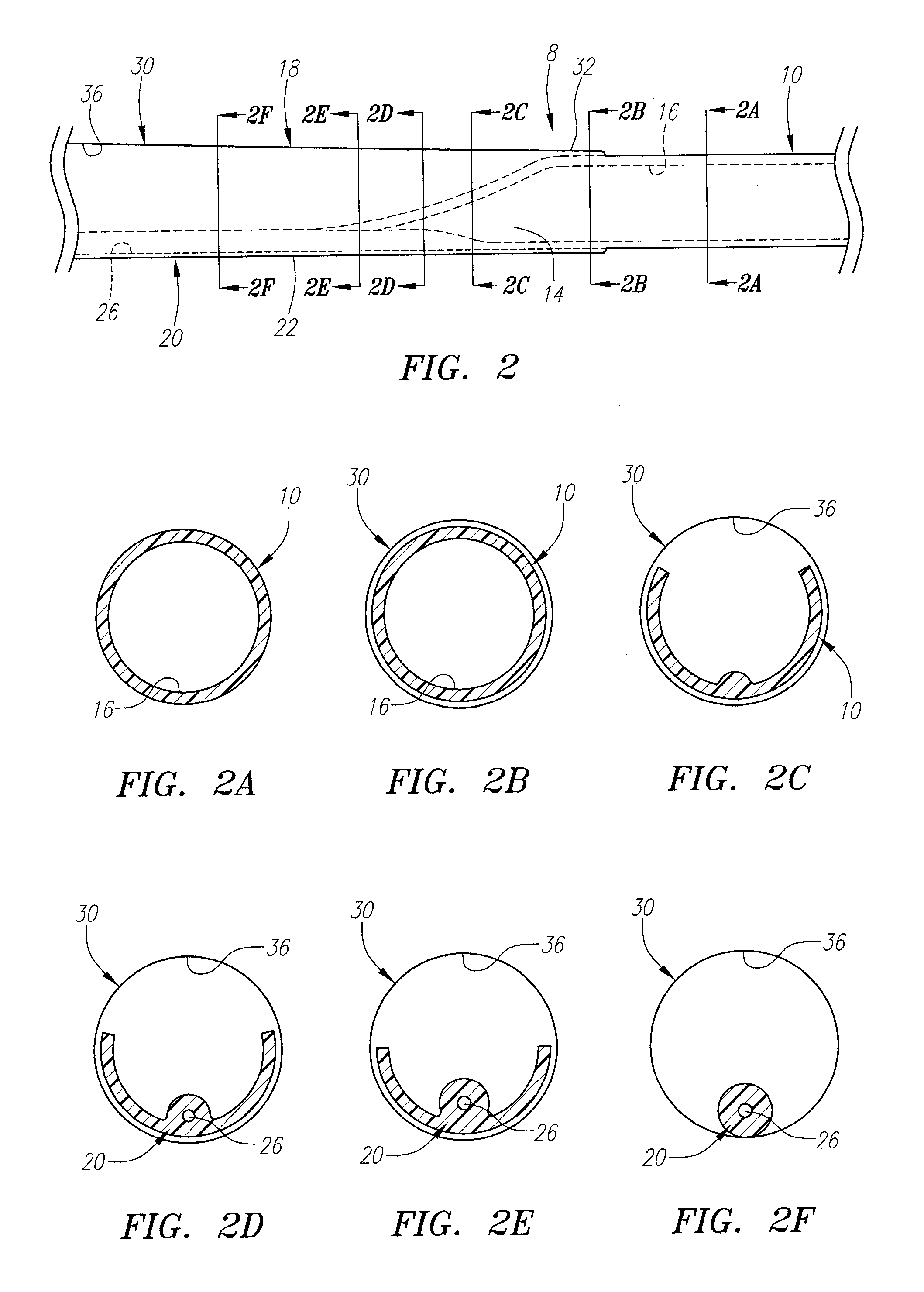
[0080] Turning to the drawings, FIGS. 1A and 1B show a first embodiment of an apparatus 8 for providing access within a body lumen (not shown) and / or for delivering one or more instruments (also not shown) within a body lumen, such as a vessel within a patient's vasculature, a passage within a patient's gastrointestinal tract, urogenital tract, respiratory tract, lymphatic system, and the like.

[0081] Generally, the apparatus 8 includes a tubular proximal portion 10 and an expandable distal portion 18. The tubular proximal portion 10 is an elongate tubular member, e.g., a catheter, sheath, and the like, including a proximal end 12, a distal end 14 sized for insertion into a body lumen, and a lumen 16 extending between the proximal and distal ends 12, 14. Optionally, the tubular proximal portion 10 may include one or more additional lumens (not shown), e.g., for receiving a guide wire, inflation media, and / or for perfusion, as described further below. Such additional lumens may be di...


PUM


Abstract

Apparatus and methods are provided for providing access to a body lumen, e.g., to deliver a pacing lead within a patient's heart. The apparatus includes a tubular member including a proximal end, a distal end sized for insertion into a body lumen, and a lumen extending therebetween. An elongate member extends from the distal end of the tubular member. An expandable sheath extends along at least a portion of the elongate member, the sheath being expandable from a contracted condition to facilitate insertion into a body lumen, and an enlarged condition wherein the sheath at least partially defines a lumen communicating with the tubular member lumen. A stylet or other shaped element is insertable into the elongate member for changing a shape of at least a distal tip of the elongate member, e.g., for accessing side branches extending from a body lumen, e.g., within a patient's coronary venous system.

Description

[0001] This application claims benefit of provisional application Ser. No. 60 / 798,915, filed May 9, 2006. This application is also a continuation-in-part of co-pending application Ser. No. 11 / 347,361, filed Feb. 3, 2006, which claims benefit of provisional applications Ser. No. 60 / 649,497, filed Feb. 3, 2005, and 60 / 752,763 filed Dec. 20, 2005, and is a continuation-in-part of co-pending application Ser. No. 10 / 958,034, filed Oct. 4, 2004 and Ser. No. 11 / 062,074 filed Feb. 17, 2005. The entire disclosures of these applications are expressly incorporated herein by reference.FIELD OF THE INVENTION [0002] The present invention relates generally to apparatus and methods for delivering instruments and / or agents during a medical procedure, and, more particularly, to apparatus and methods for delivering pacing leads or other devices, and / or for navigating and / or cannulating the coronary sinus, coronary vein branches, and / or other branches within a patient's vasculature. BACKGROUND [0003] M...

Claims


Application Information

Patent Timeline
IPC IPC(8): A61M29/00A61F2/958
CPCA61B17/3439A61M25/0097A61M25/0147A61N2001/0585A61M25/0662A61M2025/0024A61N1/056A61M25/0152
Inventor VENTURA, CHRISTINE P.PULIDO, ALFONSO N.LEEFLANG, STEPHEN A.
Owner MEDTRONIC INC
Learn More