Apparatus, system, and method for low cost high resolution chemical detection

a chemical detection and high-resolution technology, applied in the field of chemical detectors, can solve the problems of tedious and expensive process, high cost, manufacturing cost and reliability problems, etc., and achieve the effect of low cost, inexpensive and simple manufacturing

Active Publication Date: 2008-01-24
WELCH EDWARD K II
View PDF13 Cites 7 Cited by
  • Summary
  • Abstract
  • Description
  • Claims
  • Application Information

AI Technical Summary

Benefits of technology

[0016] Based on the foregoing, Applicant asserts that a need exists for a low cost high resolution chemical detector. The present invention has been developed in response to the present state of the art, and in particular, in response to the problems and needs in the art that have not yet been fully solved by currently available gas chromatography (GC) sensor technology. Accordingly, the present invention has been developed to provide an apparatus, system, and method for detects chemicals present at low concentrations in a GC sensor package that is inexpensive and simple to manufacture.

Problems solved by technology

GC sensors are extremely useful for detecting specific chemicals in a gas with mixed components, but they suffer from the major drawback that they are quite expensive.
However, the present art for accomplishing this requires complicated machining and assembly causing manufacturing expense and reliability problems.
Another limitation of the present art is that manufacture of GC columns is a tedious and expensive process.
For example, the GC column must be heated uniformly while in use, and low cost methods to effectively accomplish this uniform heating are lacking in the present art.
One current method to provide effective and affordable heating is to co-axially winding a heating element around the GC column—this method is expensive to implement.
There are temperature control methods which are easy to manufacture, but which tend to leave the GC column directly exposed to a heating element and thus allow for non-uniform temperature spikes at places along the GC column.
Another limitation of current GC sensor technology is that the sensors need to be periodically calibrated against an internal standard, and no cheap methods exist to provide for this.
Current methods of adding adsorption-desorption materials tend to cause variable pressure drop in the sensor flow paths.
This causes the temperature to be set higher than necessary when the actual ambient temperature is low, making chemical detection more difficult than required, and inducing greater energy loss to heat the GC sensor than would otherwise be required.
Further, in high resolution GC sensors that are detecting concentrations in the parts-per-million (ppm) and parts-per-billion (ppb) ranges, extraneous peaks and noise will occur in the basic signal.
This variability in peak shape makes it difficult for detection algorithms to correlate the concentrations of the various chemicals.
A dual hyphenated GC sensor, and any GC sensor that is either utilized to detect many chemicals simultaneously, or utilized to detect chemicals from a complex mixture of gases, suffers in the current art from difficulty in finding chemical elution peaks within a complex signal.
Often a significant amount of noise is produced in the signal.
Noise suppression wavelets are known in the art, but any particular noise suppression wavelet will still tend to leave some noise peaks in the signal and complex signals continue to be difficult to interpret.
Proper sealing of GC sensors is a known difficulty in the art, and is especially problematic in sensors attempting to detect chemicals at the low parts-per-million (ppm), or even into the parts-per-billion (ppb) range.

Method used


Image

  • Apparatus, system, and method for low cost high resolution chemical detection
  • Apparatus, system, and method for low cost high resolution chemical detection
  • Apparatus, system, and method for low cost high resolution chemical detection

Examples


Embodiment Construction

[0056] It will be readily understood that the components of the present invention, as generally described and illustrated in the figures herein, may be arranged and designed in a wide variety of different configurations. Thus, the following more detailed description of the embodiments of the apparatus, system, and method of the present invention, as presented in FIGS. 1 through 23, is not intended to limit the scope of the invention, as claimed, but is merely representative of selected embodiments of the invention.

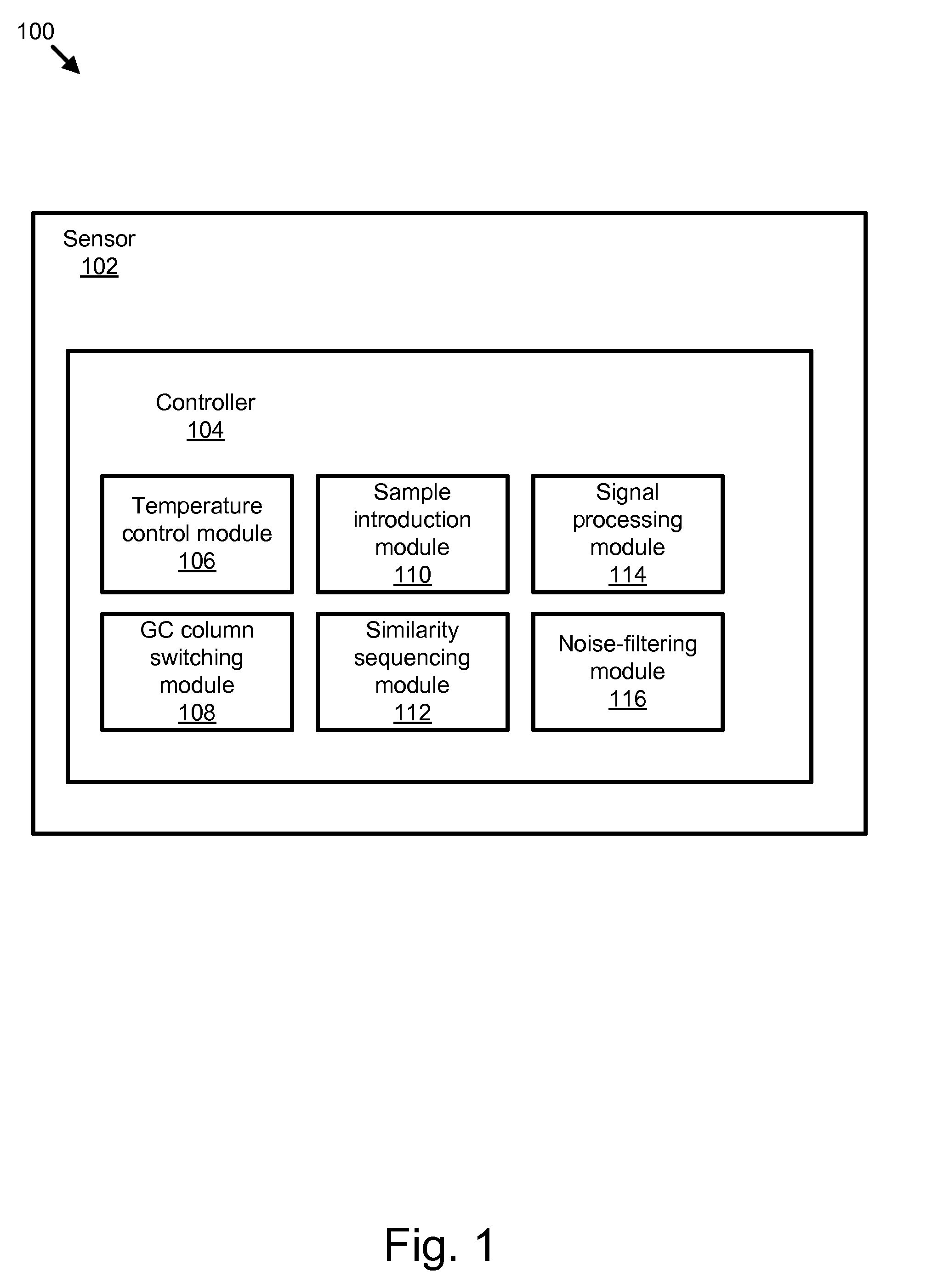
[0057] Many of the functional units described in this specification have been labeled as modules, in order to more particularly emphasize their implementation independence. For example, a module may be implemented as a hardware circuit comprising custom VLSI circuits or gate arrays, off-the-shelf semiconductors such as logic chips, transistors, or other discrete components. A module may also be implemented in programmable hardware devices such as field programmable gate a...


PUM

PropertyMeasurementUnit
temperatureaaaaaaaaaa

Abstract

An apparatus, system, and method are disclosed for low cost high resolution chemical detection. The apparatus includes two outer sealing bodies with flow channels etched into the bodies. Two gas chromatography (GC) columns are between the outer bodies, with a valve that switches flow regimes from series flow through the two GC columns to sample flowing directly to each GC column. The flow regimes are achieved with a single pump or dual pumps, and with one to three flow restrictions. The apparatus includes a preconcentration tube for concentrating chemicals of interest from the sample, and a sample switching valve and sampling pump to switch the sample flow from concentrating sample to delivering concentrated sample. The apparatus includes an engineered leak to equalize flow between a sample channel and a detector circuit. The sample channels may have impermeable inserts allowing the apparatus to measure chemicals in the parts-per-billion range.

Description

CROSS-REFERENCES TO RELATED APPLICATIONS [0001] This application claims benefit of U.S. patent application Ser. No. 60 / 805,309 entitled “APPARATUS, SYSTEM, AND METHOD FOR BROAD SPECTRUM CHEMICAL DETECTION” and filed on Jun. 20, 2006 for Arnold et al., which is incorporated herein by reference.BACKGROUND OF THE INVENTION [0002] 1. Field of the Invention [0003] This invention relates to chemical detectors and more particularly relates to gas chromatography sensors. [0004] 2. Description of the Related Art [0005] Gas chromatography (GC) is useful in the chemical industry as a separation mechanism and as a sensing mechanism. GC sensors are extremely useful for detecting specific chemicals in a gas with mixed components, but they suffer from the major drawback that they are quite expensive. [0006] The required purities in GC mandate, within most of the current art, the use of valves that cost in the thousands of dollars per valve. One concept has been introduced which allows air pressure...

Claims


Application Information

Patent Timeline
Patent Type & Authority Applications(United States)
IPC IPC(8): G01N30/20
CPCG01N30/468G01N30/461
Inventor ARNOLD, NEIL S.BODILY, GARYBODILY, KAREN
Owner WELCH EDWARD K II
Why Eureka
Try Eureka