Roller Bearing in a Roller Press

a roller press and bearing technology, applied in the field of twinroller machines, can solve the problems that the spherical roller bearing cannot readily compensate for thermal changes in the length of the roller, and achieve the effects of reducing the time it takes to exchange worn rollers, reducing assembly effort, and reducing the accuracy requirements of the machine fram

Inactive Publication Date: 2008-01-24
KHD HUMBOLDT WEDAG GMBH
View PDF6 Cites 10 Cited by
  • Summary
  • Abstract
  • Description
  • Claims
  • Application Information

AI Technical Summary

Benefits of technology

[0007] A further advantage of the guide rods respectively connecting the fixed bearing housing and the movable bearing housing lies in the simpler assembly and disassembly of the roller units, which comprise the roller and bearing housings pushed onto the bearing journals of the latter, for example by means of a crane in the case where a roller is changed, the bearing housing with the axially unfixed movable bearing not being able to slip off from the associated bearing journal because of the guide rod. In any event, the guide rod allows the rollers to be made to slant, the cylindrical roller bearings and the roller shaft remaining axially parallel even in slanted roller positions, thereby excluding the possibility of the bearing seals and labyrinthine bearing gaps gaping when the roller is made to slant.
[0008] According to one particular feature of the invention, the guide rods respectively have at their ends a pivot with a connecting arm, which acts on the respectively neighboring bearing housing. In this way, the guidance of the bearing housings comprising the movable bearings is accomplished particularly effectively in the event of a thermal change in the length of the roller and / or a slanting position of the roller. Furthermore, as a result, the system remains statically defined.
[0009] The guide rods respectively used for each roller according to the invention allow the distances between the bearing housings that are pushed onto the bearing journals to be definitively set at the workshop. There is no need for any further setting and aligning work at the installation site of the roller press or roller mill, as a result of which the assembly effort is reduced and the time it takes to exchange worn rollers is considerably reduced. Because the movable bearing housings are no longer guided by means of sliding-guide slotted links on the machine frame, in the twin-roller machine according to the invention the accuracy requirements in the production of the machine frame are reduced, which is of advantage in particular when the machine frame is produced elsewhere.
[0010] The guide rod for connecting the fixed bearing housing and the movable bearing housing may be adjustable in length, for example equipped with a turnbuckle, to make it easy to compensate for the production tolerances.

Problems solved by technology

This roller mobility may be accomplished by relatively costly spherical roller bearings installed in the bearing housings, with which however the bearing seals are subjected to excessive stresses and soiled sealing grease may be undesirably sucked into the gaping and increasingly large labyrinthine gap if the rollers are made to slant to any great extent, and with which the bearing housings are axially fixed, for example by means of adjusting springs.
Spherical roller bearings also cannot readily compensate for thermal changes in the length of the rollers.

Method used


Image

  • Roller Bearing in a Roller Press
  • Roller Bearing in a Roller Press
  • Roller Bearing in a Roller Press

Examples


Embodiment Construction

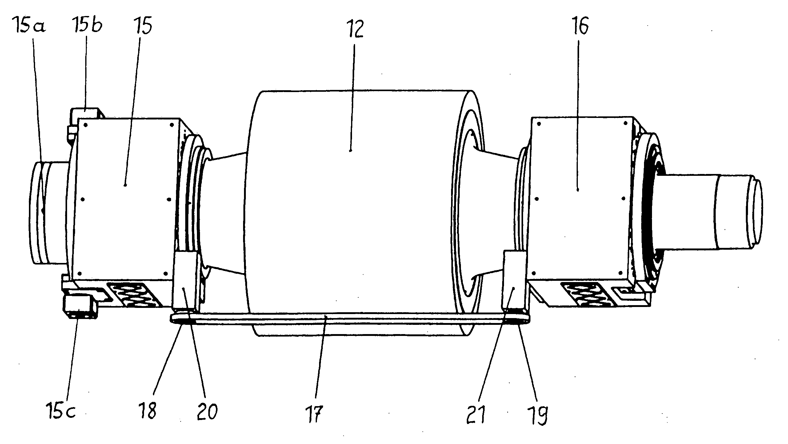
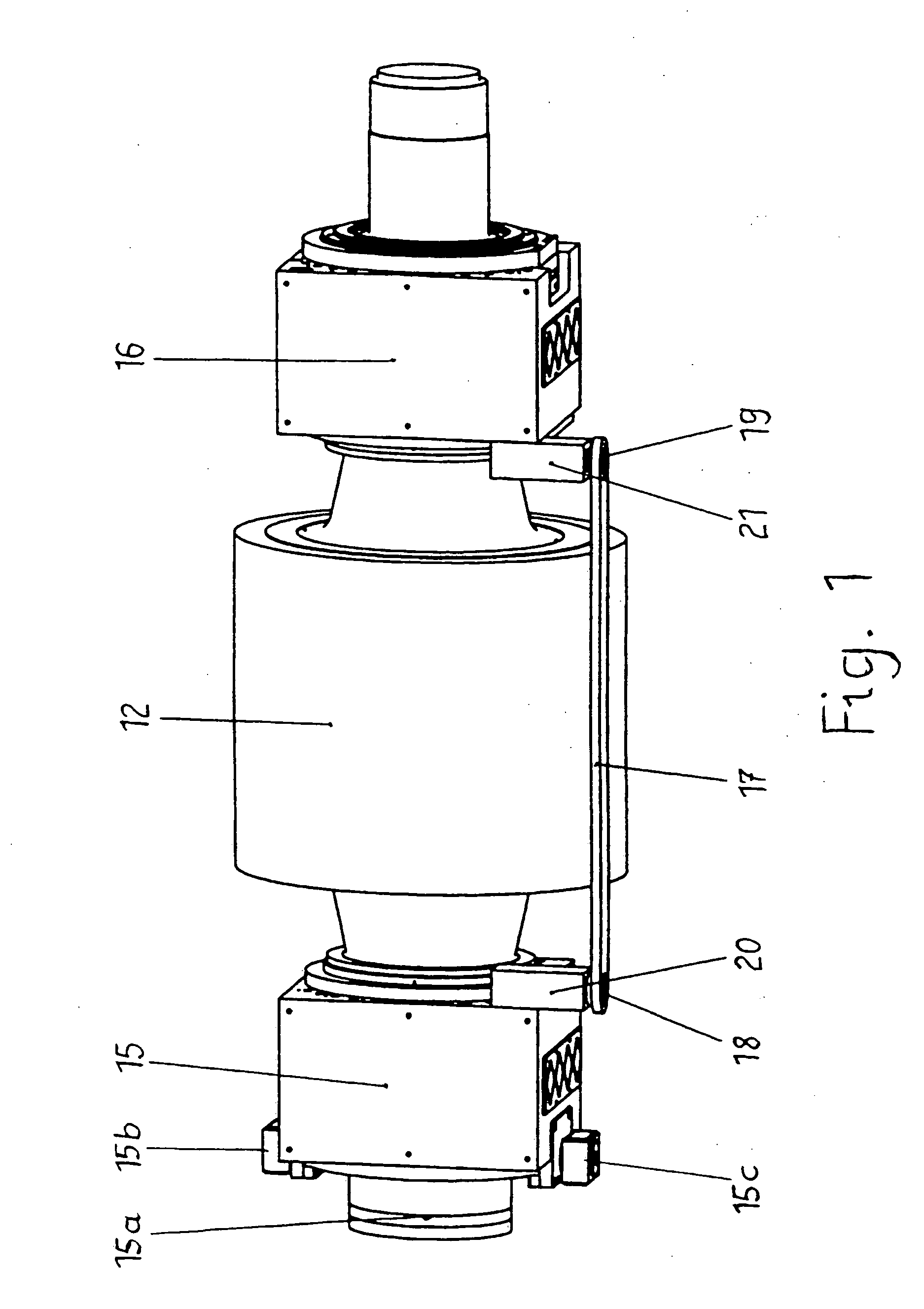
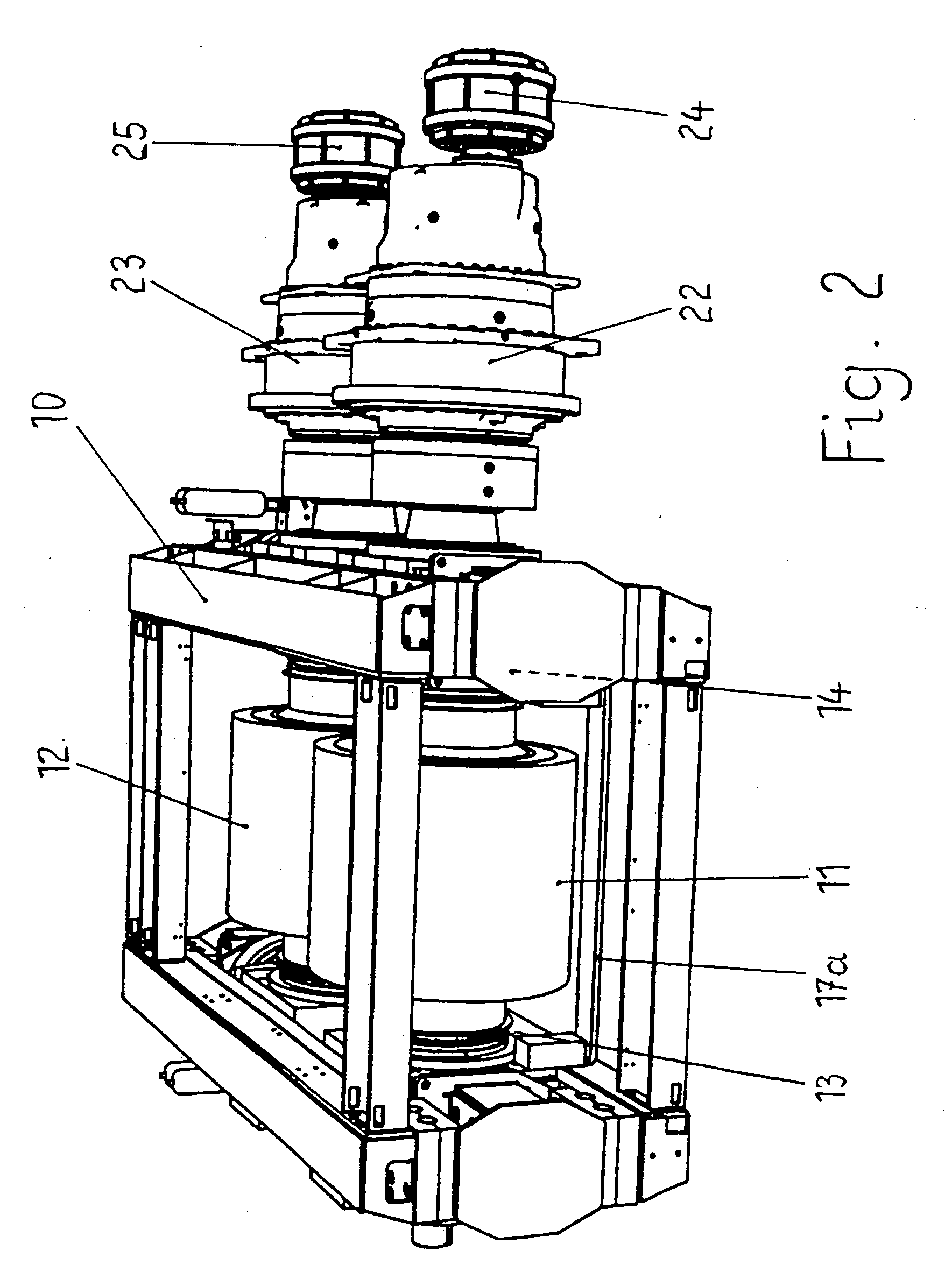
[0017] According to FIG. 2, the roller press has a machine frame 10, in which two oppositely rotating rollers 11, 12 are rotatably mounted, which form between them a roller nip 30 and one of which, for example the front roller in FIG. 2, is formed as a fixed roller 11 and the other of which, the rear roller in FIG. 2, is formed as a movable roller 12, the latter of which is drawn separately in FIG. 1. Both rollers have bearing journals, which are mounted in rolling bearings, in particular cylindrical roller bearings, which in turn are arranged in bearing housings. While the fixed roller 11 is supported with its two bearing housings directly on the front machine frame side parts and rests on two brackets 13, 14 of the machine frame 10, the movable roller 12 rests with its bearing housings 15 and 16 likewise on slideways 31, 32 of these two spaced-apart brackets 13 and 14, where it can slide back and forth transversely in relation to the roller nip 30 with its bearing housings 15, 16 ...


PUM


Abstract

The aim of the invention is to simplify and to improve mounting of roller bearings in double roller machines, for example, roller presses for interparticle comminution of granular goods. The rollers and the bearing housing thereof are formed by means of slanting rollers and/or thermal roller longitudinal changes. The rollers are guided in a secure manner on the slide guides thereof. The invention is characterized in that the fixed bearing housing and the moveable bearing housing are connected together by means of a guide rod in each roller.

Description

BACKGROUND OF THE INVENTION [0001] The invention relates to a twin-roller machine for the pressure treatment of granular material, in particular a roller press for material-bed comminution or compacting or briquetting, with two rollers which are rotatably mounted in a machine frame, are oppositely driven and are separated from each other by a roller nip, at least one of which rollers is formed as a movable roller which is movable transversely in relation to the roller nip and the bearing housings of which are supported on frame side parts by means of hydraulic cylinders, the bearing housings being mounted with their undersides on level slideways of machine brackets. [0002] In the case of such twin-roller machines, the movable roller lies with its bearing housings on the slideways of the two spaced-apart brackets, where it can slide back and forth transversely in relation to the roller nip with its bearing housings by means of sliding plates, a slanting roller position with a non-par...

Claims


Application Information

Patent Timeline
Patent Type & Authority Applications(United States)
IPC IPC(8): B30B3/04F16C13/02F16C23/08
CPCB02C4/28B30B15/04B30B3/04
Inventor SPLINTER, CHRISTIANFRANGENBERG, MEINHARD
Owner KHD HUMBOLDT WEDAG GMBH
Why Eureka
Try Eureka