Fastener driving device

a technology of driving device and fastener, which is applied in the field of power tools, can solve the problems of increasing user fatigue, affecting the use of tools, and affecting the use of tools, and achieves the effect of sufficient energy to driv

Inactive Publication Date: 2008-01-24
STANLEY FASTENING SYST LP
View PDF62 Cites 74 Cited by
  • Summary
  • Abstract
  • Description
  • Claims
  • Application Information

AI Technical Summary

Benefits of technology

[0016] It is an aspect of the present invention to provide a lightweight and e...

Problems solved by technology

Recoil negatively impacts a tool's ability to drive a fastener, and, it may also increase user fatigue.
Of course, these factors are inter-related in that if the tool does not adequately drive the fastener, recoil will typically be more severe.
One problem with a short drive time is the high power requirement it creates.
Direct chemical energy can be released in less than 10 msec., but direct chemical energy in discrete actuations has other costs and complexities that make it limited at the present time (e.g. fuel cost, exhaust gases).
However, chemical energy based tools typically cannot practically provide “bump fire” capability where the trigger is depressed, and the contact trip is depressed to start a drive sequence.
However, one recognized problem with a flywheel is long term energy storage, which creates a need to get the total required energy for a first actuation into the flywheel before the perceived actuation delay time which is approximate...

Method used


Image

  • Fastener driving device
  • Fastener driving device
  • Fastener driving device

Examples


Embodiment Construction

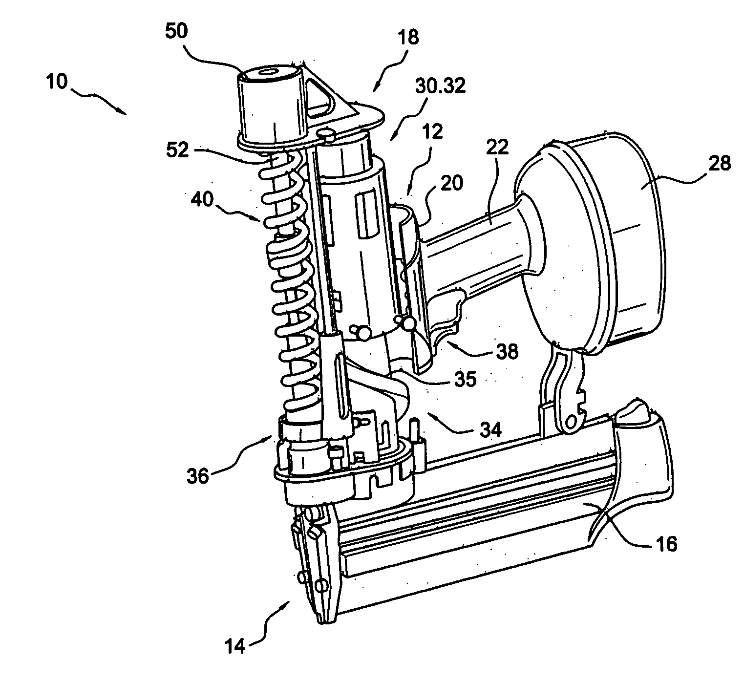
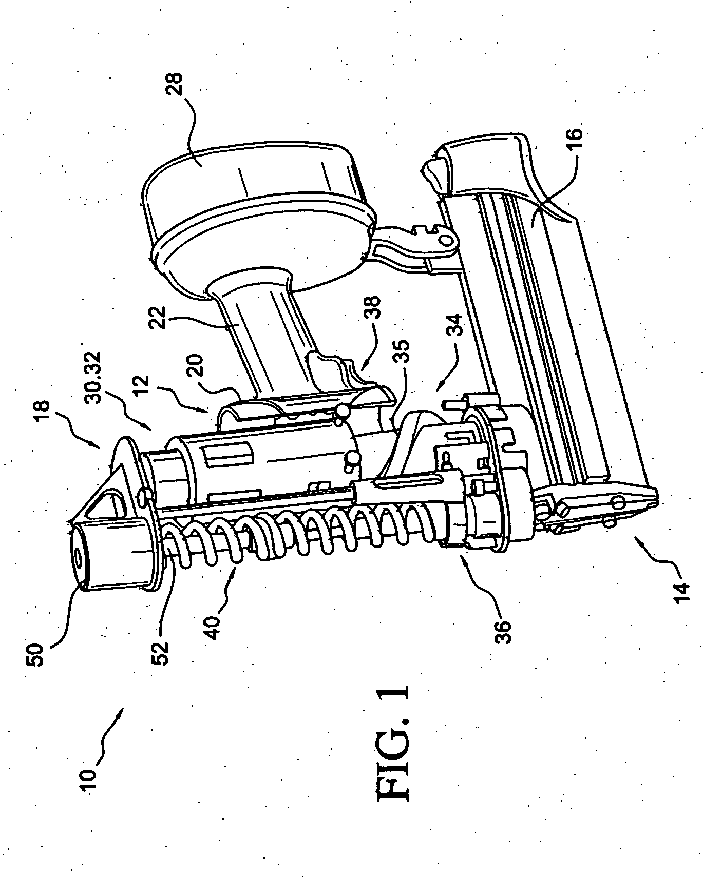
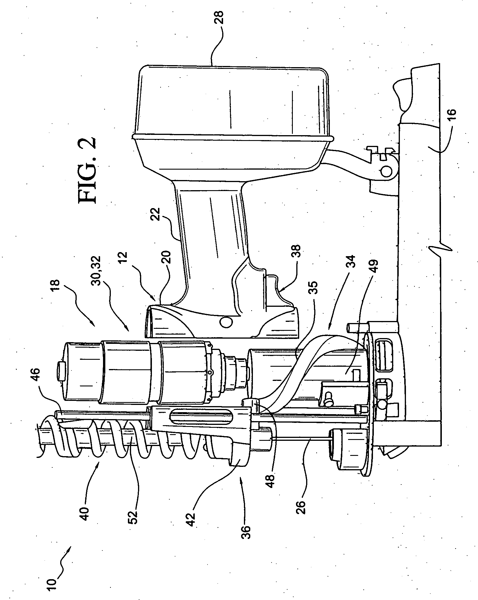
[0112]FIG. 1 illustrates a fastener driving device 10 according to one implementation of the present invention. As shown, the fastener driving device 10 includes a housing assembly 12, a nose assembly 14, and a magazine 16 that is operatively connected to the nose assembly 14 and is supported by the housing assembly 12. The device 10 also includes a power operated system 18 that is constructed and arranged to drive fasteners that are supplied by the magazine 16 into a workpiece. The housing assembly 12 includes a main body portion 20, and a handle portion 22 that extends away from the main body portion 20, as shown in FIG. 1. The majority of the main body portion 20 is removed in FIG. 1 so that features contained within the main body portion 20 may be more easily viewed. The handle portion 22 is configured to be gripped by the user of the fastener driving device 10.

[0113] The nose assembly 14 is connected to the main body portion 20 of the housing assembly 12. The nose assembly 14 ...


PUM


Abstract

A fastener driving device including a housing assembly, a nose assembly connected to the housing assembly, and a magazine for carrying a supply of fasteners that are provided to the nose assembly. The fastener driving device also includes a fastener driver and a spring that moves the fastener driver through a drive stroke. A motor and a coupler mechanism is also provided for moving the fastener driver through a return stroke.

Description

[0001] This application claims priority to U.S. Provisional Application No. 60 / 809,345 filed May 31, 2006, the contents of which are incorporated herein by reference.BACKGROUND OF THE INVENTION [0002] 1. Field of the Invention [0003] The present invention relates to power tools such as fastener driving devices. [0004] 2. Description of Related Art [0005] Fastening tools are designed to deliver energy stored in an energy source to drive fasteners very quickly. Typically fastener driving devices use energy sources such as compressed air, flywheels, and chemicals (fuel combustion & gun powder detonation). For some low energy tools, steel springs are used. For example, U.S. Pat. No. 6,899,260 discloses a small cordless brad tool. U.S. Pat. No. 6,997,367 discloses a hand held nailing tool for firing small nails. [0006] It is desirable for the tool to be of low weight so that it may be used with one hand, and not cause excessive fatigue. It is also desirable for fastener driving devices t...

Claims


Application Information

Patent Timeline
IPC IPC(8): B25C3/00
CPCB25C1/06B25C1/008
Inventor SIMONELLI, DAVIDHEWITT, CHARLES W.MILLER, KEVEN
Owner STANLEY FASTENING SYST LP
Why Eureka
Try Eureka