Liquid jet apparatus and printing apparatus

Inactive Publication Date: 2008-01-24
SEIKO EPSON CORP
View PDF73 Cites 45 Cited by
  • Summary
  • Abstract
  • Description
  • Claims
  • Application Information

AI Technical Summary

Benefits of technology

[0018] Further, by adjusting the number of the drive transistors of the digital power amplifier in accordance with the number of the actuators to be driven, the high-speed switching and the large current driving become possible.
[0019] Further it is preferable that the number of transistors adjusting unit decreases the number of the drive transistors in the case in which the number of the actuators to be driven is small, and increases the number of the drive transistors in the case in which the number of the actuators to be driven is large.
[0020] According to the liquid jet apparatus of the invention described above, the total capacitance of the transistors in the case in which the number of the actuators to be driven is small is reduced to make the high-speed switching possible, and the drive current in the case in which the number of the actuators to be driven is large is distributed to a pl

Problems solved by technology

However, in the current amplifier with such a configuration, the linear drive of the transistor itself is inefficient, a large-sized transistor is required as a measure against heating of the transistor itself, and moreover, a heat radiation plate for cooling the transistor is required, thus a disadvantage of growth in the circuit size arises, and among others, the size of the heat radiation plate for cooling constitutes a great barrier to design the layout.
However, since the DC/DC converter is, in nature, designed to generate a constant voltage, in a head drive device of the inkjet printer described in JP-A-2005-35

Method used


Image

  • Liquid jet apparatus and printing apparatus
  • Liquid jet apparatus and printing apparatus
  • Liquid jet apparatus and printing apparatus

Examples


Example

[0040] An embodiment will be explained with reference to the drawings using a printing apparatus for printing letters and images on a print medium by emitting a liquid jet, as an example of the present invention.

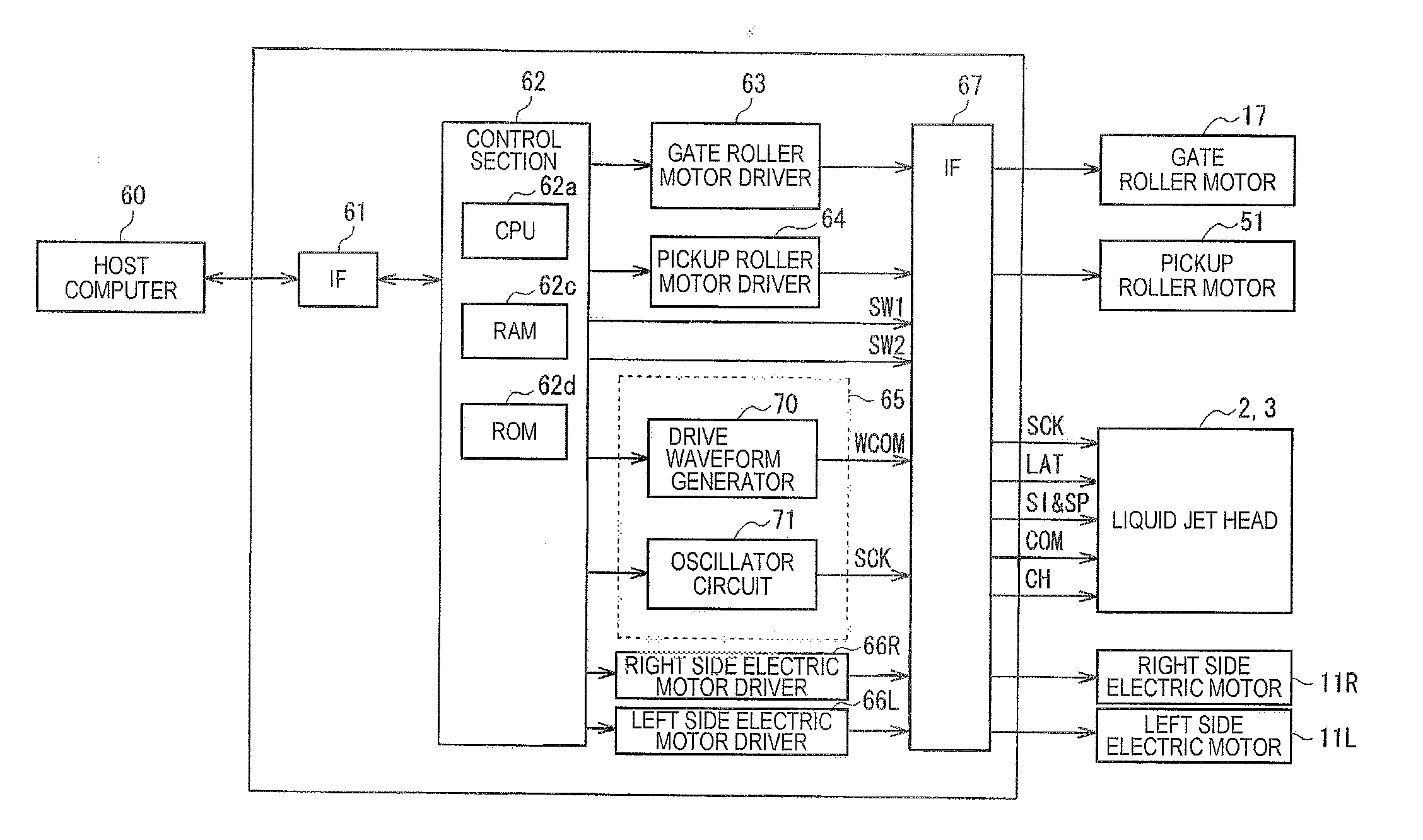
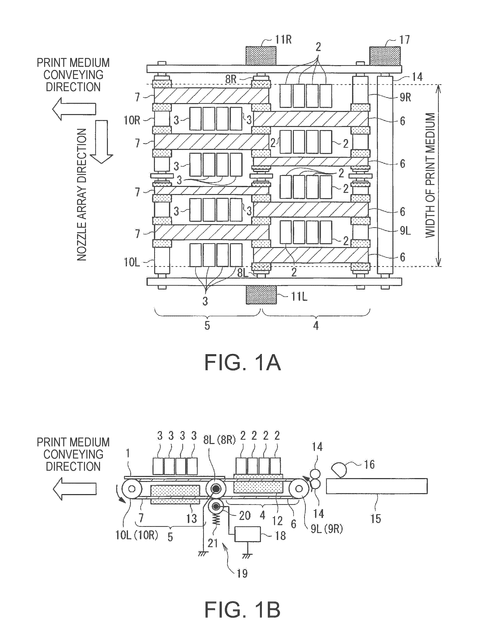
[0041]FIGS. 1A and 1B are schematic configuration views of the printing apparatus according to the present embodiment, wherein FIG. 1A is a plan view thereof, and FIG. 1B is a front view thereof. In FIG. 1, in the line head printing apparatus, a print medium 1 is conveyed from upper right to lower left of the drawing along the arrow direction, and is printed in a print area in the middle of the conveying path. It should be noted that the liquid jet head of the present embodiment is not disposed integrally in one place, but is disposed separately in two places.

[0042] The reference numeral 2 in the drawing denotes a first liquid jet head disposed on the upstream side in the conveying direction of the print medium 1, the reference numeral 3 denotes a second liquid jet head di...


PUM


Abstract

A liquid jet apparatus includes a plurality of nozzles provided to a liquid jet head, an actuator provided corresponding to each of the nozzles, and drive unit that applies a drive signal to the actuator, wherein the drive unit includes drive waveform signal generation unit that generates a drive waveform signal providing a basis of a signal for controlling the operation of the actuator, modulator unit that pulse-modulates the drive waveform signal generated by the drive waveform signal generation unit, a digital power amplifier for power-amplifying the modulated signal, which is pulse-modulated by the modulator unit, a low-pass filter for smoothing the power-amplified and modulated signal power-amplified by the digital power amplifier and supplying the actuator with the power-amplified and modulated signal as the drive signal, and carrier frequency adjusting unit that adjusts a carrier frequency of the pulse modulation by the modulator unit in accordance with the number of the actuators to be driven.

Description

BACKGROUND [0001] 1. Technical Field [0002] The present invention relates to a liquid jet apparatus and printing apparatus arranged to print predetermined letters and images by emitting microscopic droplets of liquids from a plurality of nozzles to form the microscopic particles (dots) thereof on a printing medium. [0003] 2. Related Art [0004] An inkjet printer as one of such printing apparatuses, which is generally low-price and easily provides high quality color prints, has widely been spreading not only to offices but also to general users along with the widespread of personal computers or digital cameras. [0005] Further, in recent inkjet printers, printing in fine tone is required. Tone denotes a state of density of each color included in a pixel expressed by a liquid dot, the size of the liquid dot corresponding to the color density of each pixel is called a tone grade, and the number of the tone grades that can be expressed by the liquid dot is called a tone number. The fine t...

Claims


Application Information

Patent Timeline
IPC IPC(8): B41J29/38B41J2/30
CPCB41J2/04541B41J2/0455B41J2/04581B41J2/04568B41J2/04593B41J29/38B41J2/04588B41J2/04596
Inventor OSHIMA, ATSUSHITABATA, KUNIO
Owner SEIKO EPSON CORP
Why Eureka
Try Eureka