Configurable heat sink with matrix clipping system

a heat sink and matrix clipping technology, applied in the direction of cooling/ventilation/heating modification, semiconductor/solid-state device details, semiconductor devices, etc., can solve the problems of limited size, performance and unitary construction, and achieve the effect of reducing assembly time, documentation and inventory costs, and maximum flexibility

Inactive Publication Date: 2008-01-24
LIU KECHUAN
View PDF19 Cites 22 Cited by
  • Summary
  • Abstract
  • Description
  • Claims
  • Application Information

AI Technical Summary

Benefits of technology

[0009]A heat sink apparatus for use with electronic components or devices comprises a base portion and at least one security portion. The base portion is configured to have at least one receiving aperture and at least one heat-conducting surface. The base portion further has fins attached to its opposite side of heat-conducting surface. The base portion and the security portion are of unitary and compact construction. The security portion comprises a camming bar and a spring clip. The camming bar is configured to rotate about an axis of the spring clip to effect camming mechanism, and the spring clip has an auto-aligning feature for aligning the electronic component when engaging in assembly. The security portion is configured to flex about its axis resiliently to effect an engaged relation with the heat conducting surface to substantially fixedly maintain the electronic components in abutting relation with the heat dissipating surface. The electronic components can be assembled onto or disassembled from the heat sink assembly easily without the needs of tools and fixtures.
[0010]The unitary construction for a heat sink apparatus according to the present invention avoids the necessity for additional assembly parts such as screws, nuts, bolts, washers and adhesives. The heat sink apparatus of the present invention also avoids the requirement for such separate attachments as spring clips and fixtures suitable for clipping mechanism. In such all-in-one solution heat sink apparatus, it greatly reduces the assembly time, documentation and inventory costs.
[0011]The unitary construction for a heat sink apparatus according to the present invention provides the maximum flexibility for circuit design and printed circuit or wiring board layouts. The heat sink apparatus of the present invention also provides the flexibility to accommodate the technologies changes in IC packaging.
[0012]It is a further object of the present invention to provide a heat sink apparatus that the assembly of security portion and the base portion together to create unitary construction uses the very cost effective operations without requiring expensive equipment, tooling, skilled workers and complicated fixtures. It is, therefore, an object of the present invention to provide a heat sink apparatus that is of unitary construction using cost-effective secondary assembly operations.
[0013]It is yet a further object of the present invention to provide a heat sink apparatus that may be assembled with an associated electronic component without unnecessary assembly steps, such as ancillary process operations like drilling or tapping apertures.
[0014]It is yet a further object of the present invention to provide a heat sink apparatus that can be mounted (or soldered) onto a printed circuit or wiring board using through-hole technology without the needs to change heat sink fabricating and assembling procedures.

Problems solved by technology

These extruded heat sinks with clamps are good examples for improving ease of assembly and scalability, but are limited in the size, performance and unitary construction.

Method used


Image

  • Configurable heat sink with matrix clipping system
  • Configurable heat sink with matrix clipping system
  • Configurable heat sink with matrix clipping system

Examples


Embodiment Construction

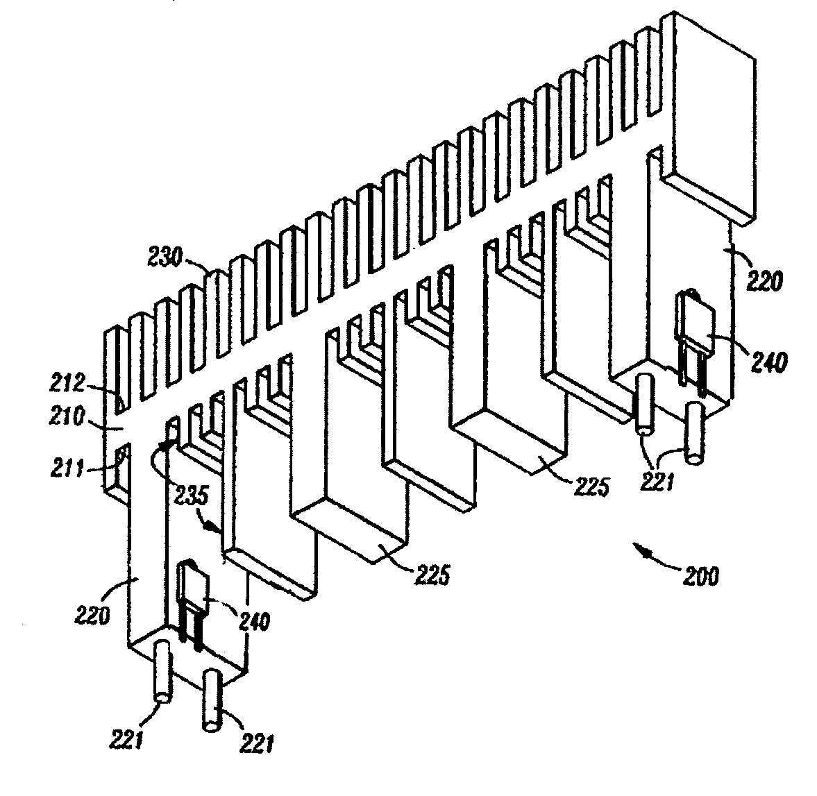
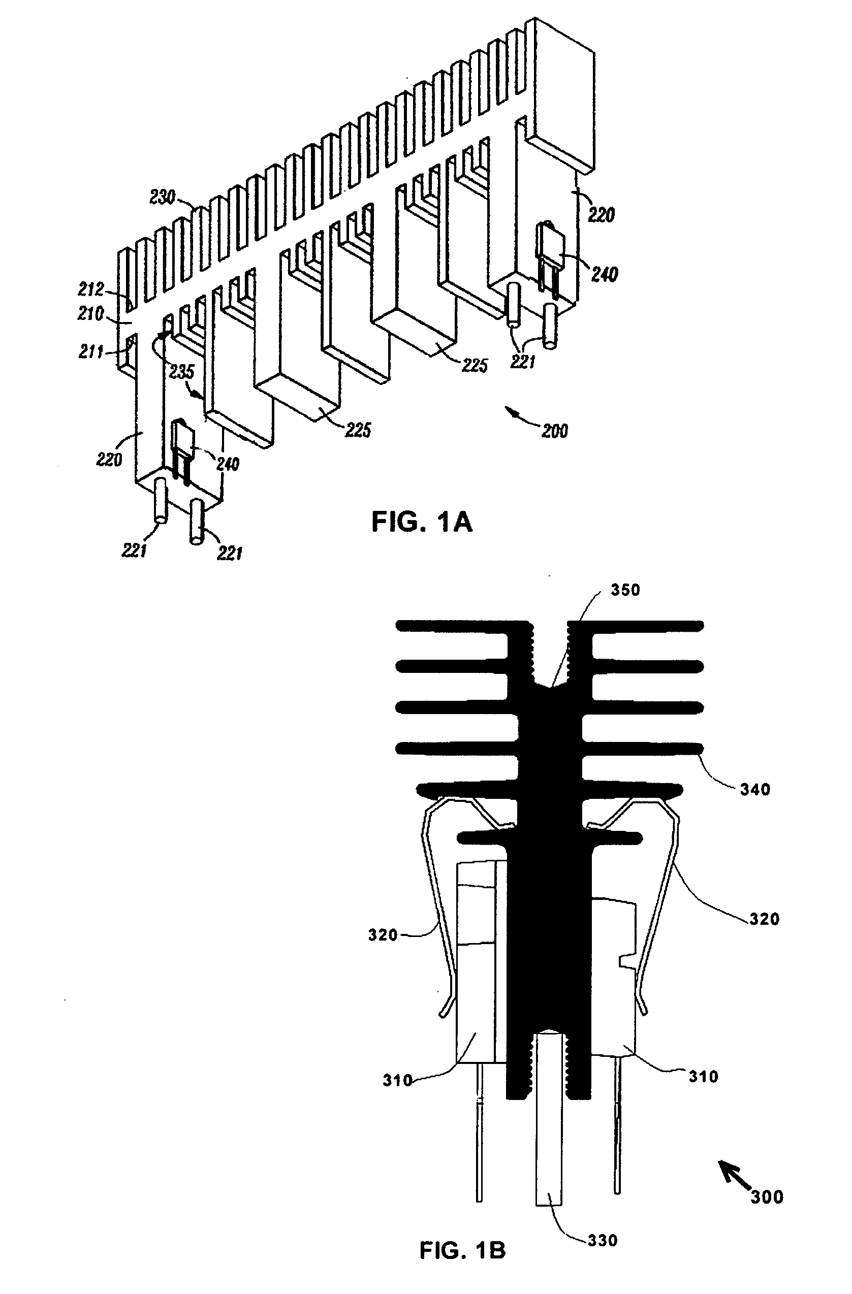
[0021]Referring initially to FIGS. 1A and 1B, illustrated are examples of prior art heat sinks 200, 300. The prior art heat sink 200 illustrated in FIG. 1A has a longitudinal spine 210 with an opposing first side 211 and second side 212. Extending from the first side 211 of the spine 210 are electronic device support legs 220, 225, configured so that each leg 220, 225 can support two electronic devices or components on opposing side of the support legs 220, 225, as shown, an electronic component 240 mounted a clip (not shown here), Multiple cooling fins 230, 235 are extending from the second side 212 and first side 211 of the spine 210. Apparently this heat sink has the disadvantages of: 1) fixed position for mounting an electrical component with given printed wiring or circuit layout; 2) lack of unitary construction since the clip is a separated part; and 3) secondary machining operation is required to make the port for receiving pin 221, if the heat sink is manufactured by extrusi...


PUM


Abstract

A heat sink apparatus for use with electronic components comprises a base portion and at least a securing portion. The base portion and the securing portion are of unitary construction. The base portion is configured to have at least one receiving aperture and one heat-conducting surface with fins extended from or attached to its opposite surface. The securing portion is a unitary construction which comprises a cam element and spring clip with auto-align and camming mechanism features. The securing portion is configured to have partially constrained with the base portion, and to be slide along the length direction for dynamic location of electronic device on heat sink. The cam element can be rotated about its cylindrical feature axis resiliently to effect an engaged relation to substantially fixedly maintain the electronic component in abutting relation with heat-conducting surface.

Description

CROSS-REFERENCE TO RELATED APPLICATIONS[0001]NoneSTATEMENT REGARDING FEDERAL SPONSORED RESEARCH OR DEVELOPMENT[0002]Not ApplicableFIELD OF THE INVENTION[0003]This invention generally relates to the art of heat sink assemblies and, particularly, to a heat sink assembly having an embedded camming clip system comprising camming and auto-align mechanisms configured to provide attachment and alignment of electronic components thereto heat sink body without requiring additional separate partsBACKGROUND OF THE INVENTION[0004]Heat sinks or heat sink assemblies of a wide variety of designs have been employed to dissipate heat generated by electronic components and devices on printed wiring or circuit boards to prevent the electronic components and devices from failure due to over heating. More than ever before, today's electronic products are reducing the size and cost, increasing power and speed dramatically, and upgrading frequently with new technologies. So that the heat sinks or heat sin...

Claims


Application Information

Patent Timeline
Patent Type & Authority Applications(United States)
IPC IPC(8): H05K7/20
CPCH01L23/367H01L23/4093H01L2924/0002H01L2924/00
Inventor LIU, KECHUAN
Owner LIU KECHUAN
Why Eureka
Try Eureka