Side type backlight module

a backlight module and side-type technology, applied in waveguides, lighting and heating apparatuses, instruments, etc., can solve the problems of limited flattening capability, partial color shift, insufficient color saturation, etc., and achieve the effect of improving color saturation

Inactive Publication Date: 2008-01-24
CPT TECH GRP
View PDF3 Cites 18 Cited by
  • Summary
  • Abstract
  • Description
  • Claims
  • Application Information

AI Technical Summary

Benefits of technology

[0011]Accordingly, an objective of the present invention is to provide a side type backlight module, so as to improve the color saturation.

Problems solved by technology

However, the rising “environmental protection” awareness is against its power consumption and radiation disadvantage, and the limited flattening capability is against the market demands of light, thin, short, small, chic, and power-saving displays.
The LCD display adopting the conventional side type backlight module may cause problems such as insufficient color saturation.
However, since the lights emitted by the green LED 120g, the red LED 120r, and the blue LED 120b cannot be fully uniformly blended in the LGP, a partial color shift may occur in the LCD display adopting the side type backlight module.

Method used


Image

  • Side type backlight module
  • Side type backlight module
  • Side type backlight module

Examples


first embodiment

The First Embodiment

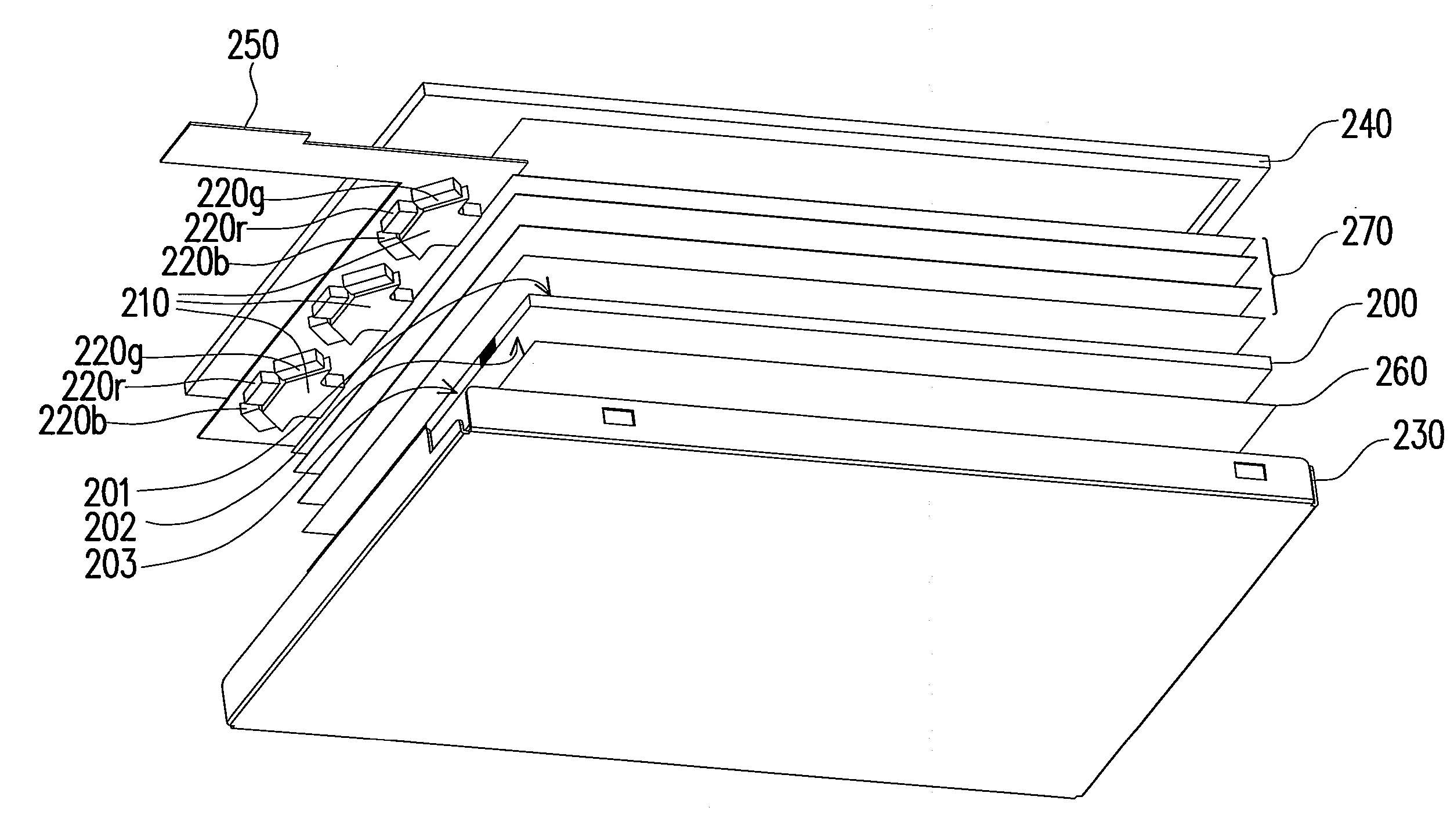
[0044]FIG. 2A is an exploded view of the side type backlight module of the first embodiment of the present invention, and FIG. 2B is a top view of the second LGP of FIG. 2A. Referring to FIG. 2A and FIG. 2B, the side type backlight module of the present embodiment comprises a first LGP 200, a plurality of second LGPs 210, a plurality of red point light sources 220r, a plurality of blue point light sources 220b, and a plurality of green point light sources 220g. The first LGP has a first light emitting surface 201, a bottom surface 202, and a first light incident surface 203 connecting the first light emitting surface 201 and the bottom surface 202. Moreover, the second LGPs 210 are disposed beside the first light incident surface 202. The red point light sources 220r, blue point light sources 220b, and green point light sources 220g are respectively disposed beside the second LGPs 210. Therefore, the lights emitted by the red point light sources 220r, the blue po...

second embodiment

The Second Embodiment

[0051]The structure of the backlight module of the second embodiment is substantially the same as that of the backlight module of the first embodiment, while the main difference is that the structure of the second LGPs 310 is different.

[0052]FIG. 3 is a top view of the second LGP of the second embodiment of the present invention. Referring to FIG. 3, the second LGP 310 has a second light emitting surface 311, a first subsidiary light incident surface 312, a second subsidiary light incident surface 313, a third subsidiary light incident surface 314, and two side surfaces 315, 316. The first subsidiary light incident surface 312 is opposite to the second light emitting surface 311, and the first subsidiary light incident surface 312 connects the second subsidiary light incident surface 313 and the third subsidiary light incident surface 314. The side surface 315 is connected between the second light emitting surface 311 and the second subsidiary light incident sur...

third embodiment

The Third Embodiment

[0054]The structure of the backlight module of the third embodiment is substantially the same as that of the backlight module of the first embodiment, while the main difference is the different structure of the second LGPs 410.

[0055]FIG. 4 is a top view of the second LGP of the third embodiment of the present invention. Referring to FIG. 4, the second LGP 410 of the present embodiment has a second light emitting surface 411 and a second light incident surface 412. The second light incident surface 412 is a curved surface, and the second light emitting surface 411 can be a plane. However, the second light emitting surface 411 can also be a convex surface or a concave surface with a curvature different from that of the second light incident surface 412. Moreover, the red point light sources 420r, the green point light sources 420g, and the blue point light sources 420b are disposed beside the second light incident surface 412.

[0056]More particularly, the curvature ...


PUM


Abstract

A side type backlight module including a first light guide plate (LGP), a plurality of second LGPs, a plurality of red point light sources, a plurality of green point light sources, and a plurality of blue point light sources is provided. The first LGP has a first light emitting surface, a bottom surface, and a first light incident surface connecting the first light exit surface and the bottom surface. The second LGPs are disposed beside the first light incident surface. Further, a plurality of red, green, and blue point light sources is respectively disposed beside the second LGPs. The lights emitted by the red point light sources, the green point light sources, and the blue point light sources are blended to be a white light by each of the second LGPs and then incident to the first light incident surface.

Description

BACKGROUND OF THE INVENTION[0001]1. Field of Invention[0002]The present invention relates to a backlight module. More particularly, the present invention relates to a side type backlight module.[0003]2. Description of Related Art[0004]In response to the increasing demand of displays, the manufacturers in the industry put great efforts in the development of displays. Among the displays, the cathode ray tube (CRT) has dominated the display market for many years due to its high display quality and mature technology. However, the rising “environmental protection” awareness is against its power consumption and radiation disadvantage, and the limited flattening capability is against the market demands of light, thin, short, small, chic, and power-saving displays. Therefore, the thin film transistor liquid crystal display (TFT-LCD), having superior properties such as high image quality, good space utilization, low power consumption, and no radiation, has become the mainstream display produ...

Claims


Application Information

Patent Timeline
Patent Type & Authority Applications(United States)
IPC IPC(8): F21V7/04
CPCG02B6/002G02B6/0073G02B6/0068G02B6/0028Y10S385/901
Inventor CHANG, WEI-YUHSIEH, JU-YIHSIAO, CHIH-CHUN
Owner CPT TECH GRP
Why Eureka
Try Eureka