Image processing apparatus and image processing method

Active Publication Date: 2008-01-24
SOVEREIGN PEAK VENTURES LLC
View PDF9 Cites 13 Cited by
  • Summary
  • Abstract
  • Description
  • Claims
  • Application Information

AI Technical Summary

Benefits of technology

[0022] Furthermore, it is possible that the gradation conversion unit outputs 0 as the converted difference, when the absolute value of the difference is larger than a second threshold value. With this, it is possible to prevent a masking signal from being added to the level difference indicating an edge component of an image.
[0023] Furthermore, it is possible that the gradation conversion unit outputs, as the converted difference, a value obtained by decreasing the absolute value of the difference at a fixed ratio. With this, it is possible to maintain a level difference to a certain extent after adding a masking signal by limiting the degree of smoothing a level difference, and thus to prevent image blurring.
[0024] Furthe

Problems solved by technology

However, the aforementioned techniques have the following problem.
By uniformly adding the random numbers to an enti

Method used


Image

  • Image processing apparatus and image processing method
  • Image processing apparatus and image processing method
  • Image processing apparatus and image processing method

Examples


Example

First Embodiment

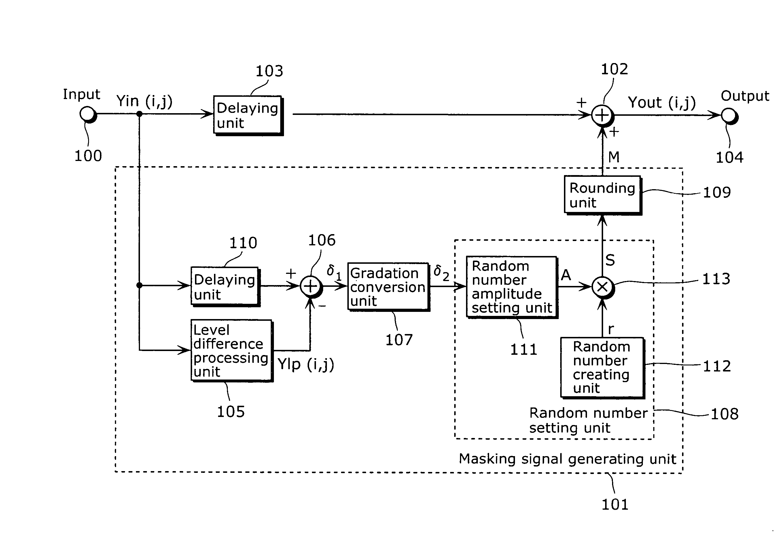
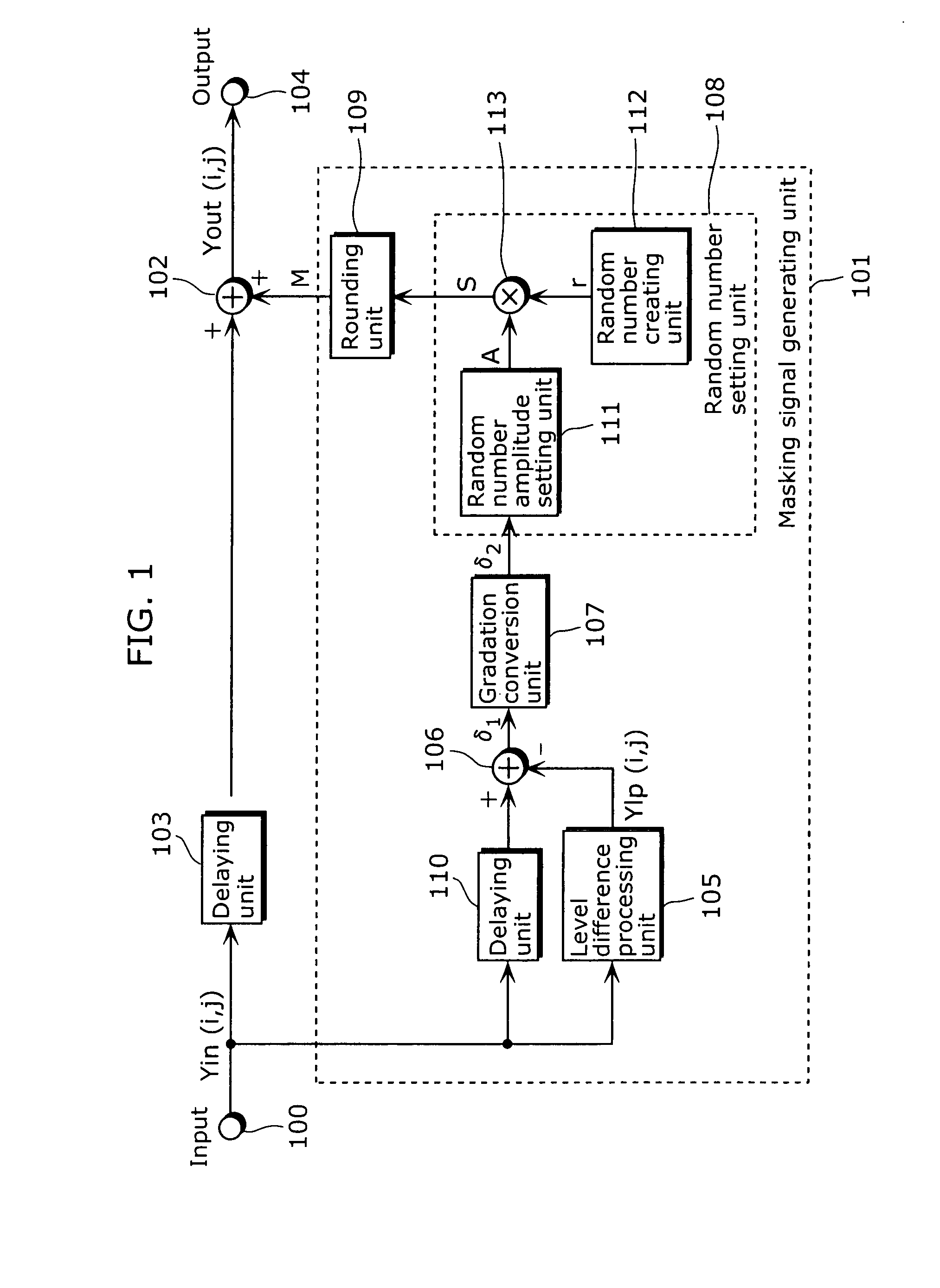
[0054]FIG. 1 schematically shows an embodiment of an image processing apparatus and an image processing method of the present invention. The image processing apparatus shown in the diagram is an apparatus which adds a masking signal including a random number to an image signal of an input image, and includes an input unit 100, a masking signal generating unit 101, a masking signal adding unit 102, a delaying unit 103, and an output unit 104.

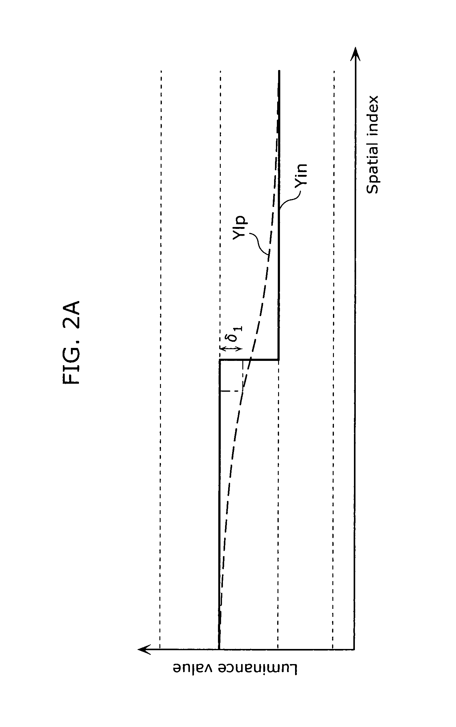
[0055] An image signal Yin (i, j) which is an integer value is inputted into the input unit 100. In a portion of the image signal Yin (i, j) where contouring or block distortion is obvious, a luminance level difference appears as shown by a solid line in FIG. 2A. By adding the random numbers shown in FIG. 2B to such portion, it is possible to make it difficult to perceive the contouring and the block distortion. Note that noise is increased when a random number is added to a flat portion. FIG. 2C shows a diagram of a signal obta...

Example

Second Embodiment

[0077]FIG. 7 is a block diagram showing an embodiment of the image processing apparatus and the image processing method of the present invention, when a luminance level difference caused by the contouring or block distortion is visually smoothed. The configuration of the diagram differs in that a random number expected value setting unit 801 is newly added, compared to the configuration in FIG. 1. The description similar to FIG. 1 is omitted, and different points are mainly described hereinafter.

[0078] Compared to the configuration in FIG. 1, an expected value of the created masking signal M can be controlled by adding the random number expected value setting unit 801 to the masking signal generating unit 101 in the configuration of FIG. 7. The random number expected value setting unit 801 outputs, to the rounding unit 109, a signal S2 obtained by subtracting, from a signal S1 inputted from the multiplying unit 113, a signal δ2 inputted from the gradation conversi...

Example

Third Embodiment

[0086]FIG. 11 is a block diagram showing an embodiment of the image processing apparatus and the image processing method, when the contouring or block distortion becomes visually less obvious while preventing an adverse effect, such as image blurring and increase of unnecessary noise, by controlling a masking signal based on local visual characteristics of an image. The configuration of the diagram differs from the configuration shown in FIG. 7 in that a visual characteristic analyzing unit 1101, a gradation conversion parameter setting unit 1102, and a random number amplitude parameter setting unit 1103 are newly added. The description similar to FIG. 7 is omitted, and different points are mainly described hereinafter.

[0087] The visual characteristic analyzing unit 1101 outputs a visual characteristic analytical parameter P that controls a parameter for gradation conversion and for controlling an amplitude of a random number by analyzing local characteristics of t...


PUM


Abstract

The prevent invention can prevent roughness in an image and reduce contouring and coding distortion in the image. The image processing apparatus according to the present invention reduces distortion in an input image, and includes: a masking signal generating unit 101 that generates a masking signal for reducing the distortion; and a masking signal adding unit 102 that adds the masking signal to the input image, wherein the masking signal generating unit 101 includes: a level difference processing unit 105 that smoothes a level difference between pixel values of pixels in the input image; a difference calculating unit 106 that calculates a difference between the input image and an image which has been processed by the level difference processing unit 105; and a random number setting unit 108 that sets an amplitude, creates a is random number having the set amplitude, the amplitude decreasing, as the difference approaches a predetermined value.

Description

BACKGROUND OF THE INVENTION [0001] (1) Field of the Invention [0002] The present invention relates to an image processing apparatus and an image processing method for reducing contouring and coding distortion in a digital image signal. [0003] (2) Description of the Related Art [0004] Since a quantization error occurs in the processing using a digital signal, there are cases where distortion occurs in an output signal even when the input signal varies smoothly. The distortion is viewed as contouring on an image, and degrades the image quality. In particular, when gradation conversion processing that performs contrast enhancement on an image is performed, there are cases where image quality degradation due to the quantization error becomes a serious problem. [0005] Furthermore, an image which is compressed using the Moving Picture Expert Group (MPEG) standard is obtained by quantizing a Discrete Cosine Transform (DCT) coefficient that is obtained by calculating a luminance signal of t...

Claims


Application Information

Patent Timeline
IPC IPC(8): G06K9/40
CPCH04N19/90H04N19/86
Inventor TAKITA, KENJIKONDO, SATOSHIMONOBE, YUSUKEKUWAHARA, YASUHIRO
Owner SOVEREIGN PEAK VENTURES LLC
Why Eureka
Try Eureka