

Endoscope hood
- Summary
- Abstract
- Description
- Claims
- Application Information
AI Technical Summary
Benefits of technology
Problems solved by technology
Method used
Image

Examples
Embodiment Construction
[0041]Hereinafter, an endoscope hood according to preferred embodiments of the presently disclosed subject matter is described in detail with reference to the accompanying drawings.
[0042]Overall Configuration
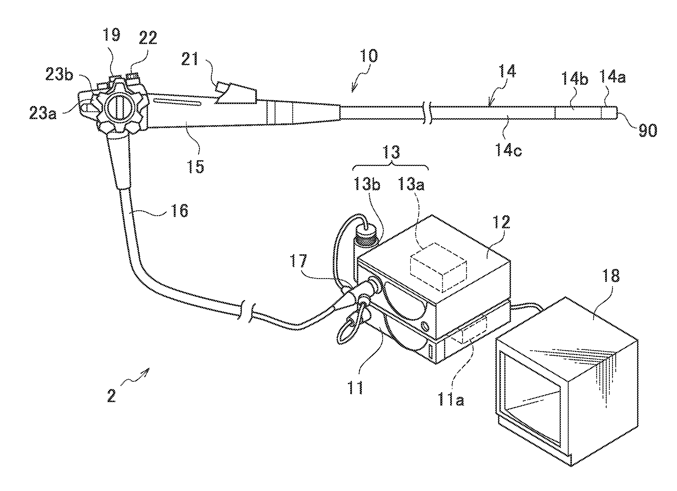
[0043]FIG. 1 is an overall configuration view illustrating an endoscope system. An endoscope system 2 illustrated in FIG. 1 includes an endoscope apparatus (endoscope) 10, a processor apparatus 11, a light source apparatus 12 and an air supply / water supply apparatus 13. The air supply / water supply apparatus 13 includes an air supply pump 13a incorporated in the light source apparatus 12 and a washing water tank 13b provided outside of the light source apparatus 12.
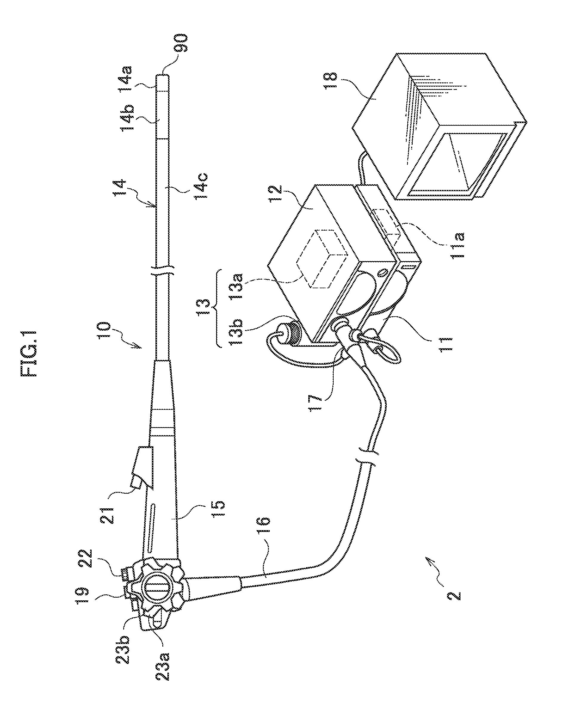
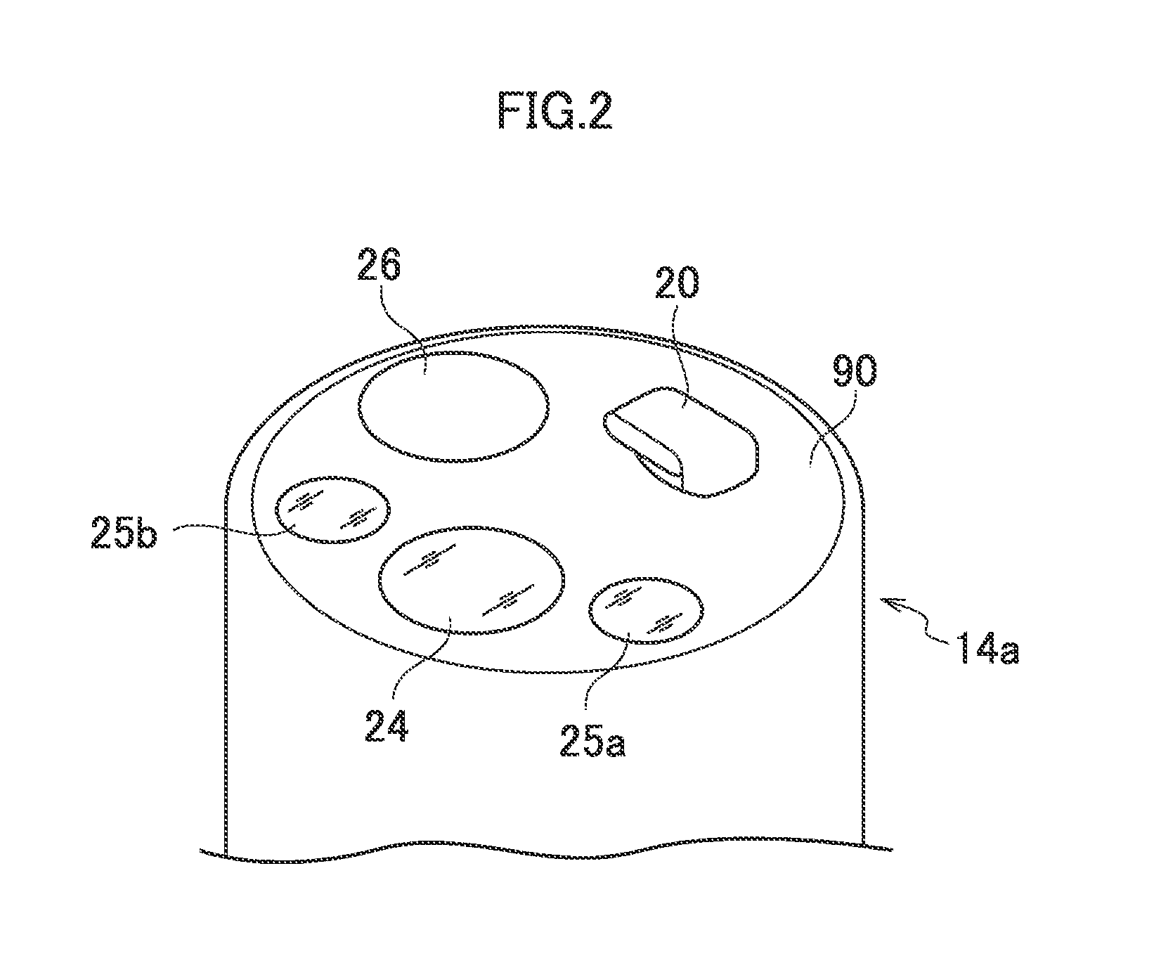
[0044]The endoscope 10 includes an insertion part 14, an operation part 15, and a universal code 16. The insertion part 14 is a part to be inserted into a body cavity of a patient (body to be examined), and includes a leading end part 14a, a bending part 14b, and a flexible tube part 14c which are connected in the stat...
PUM
 Abstract
Description
Claims
Application Information