

Straddle Mount Connector
a connector and cable mount technology, applied in the direction of coupling device connection, coupling device details, printed circuits, etc., can solve the problems of reducing the antenna effect, requiring scrapping of entire boards, and requiring laborious and time-consuming process of making sure, so as to reduce the antenna effect and eliminate the problem
- Summary
- Abstract
- Description
- Claims
- Application Information
AI Technical Summary
Benefits of technology
Problems solved by technology
Method used
Image

Examples
Embodiment Construction
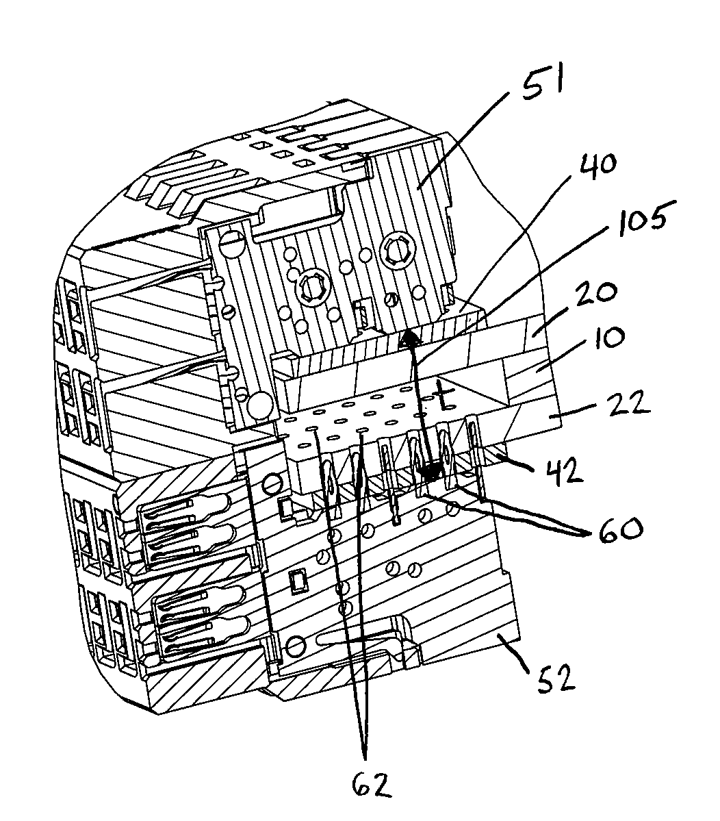
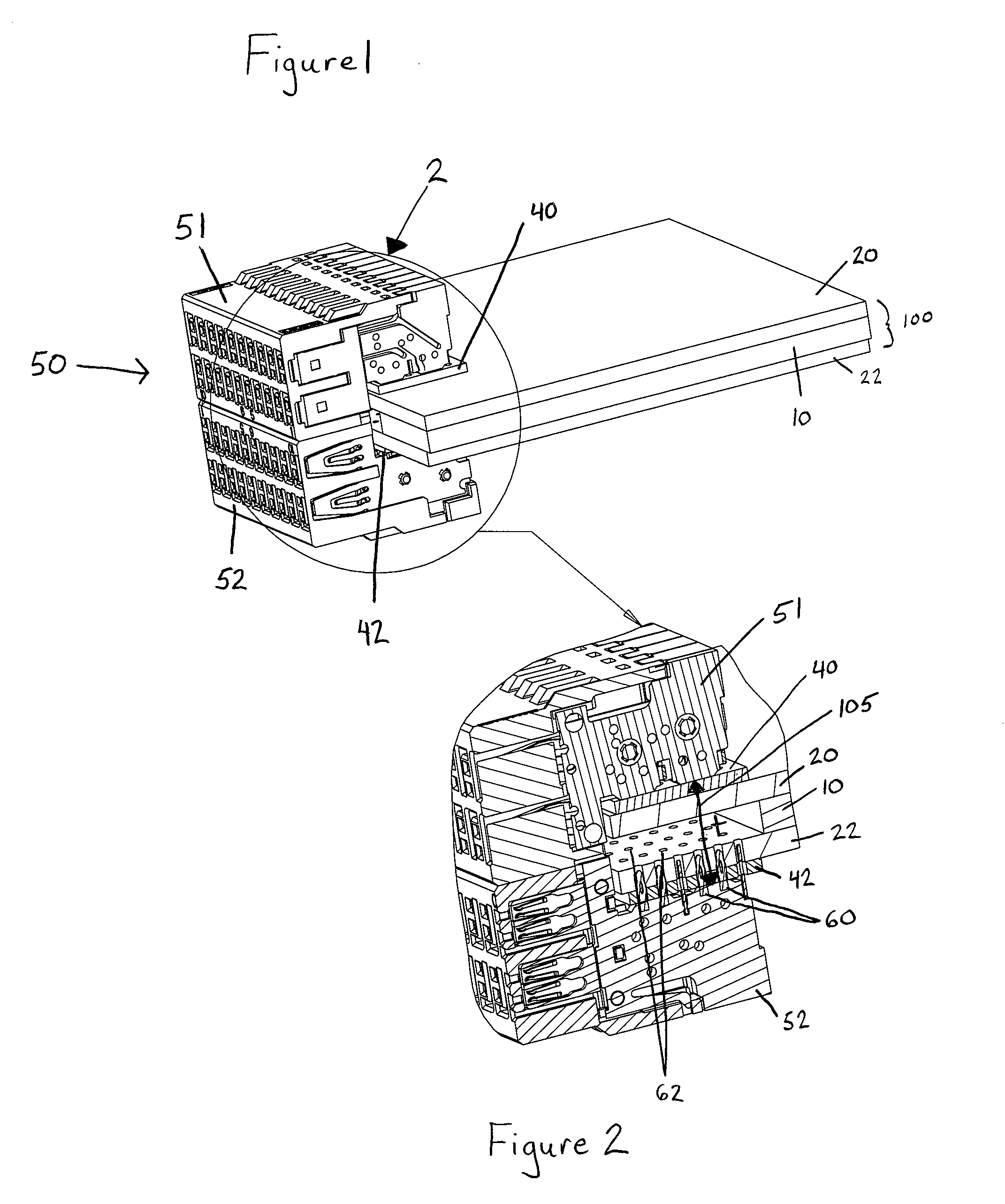
[0020]FIG. 1 illustrates a perspective view of a straddle mount connector 50 mounted on an electrical card 100 in accordance with an exemplary embodiment of the invention. The electrical card 100 comprises a heat sink member 10, a first electrical panel member 20 and a second electrical panel member 22, each of which electrical panel members are preferably printed circuit boards (PCBs). The straddle mount connector 50 comprises a first substantially rigid connector portion 51 and a second substantially rigid connector portion 52. Each connector portion 51, 52 is separately in electrical contact with a single electric panel member 20, 22 of the electrical card 100.
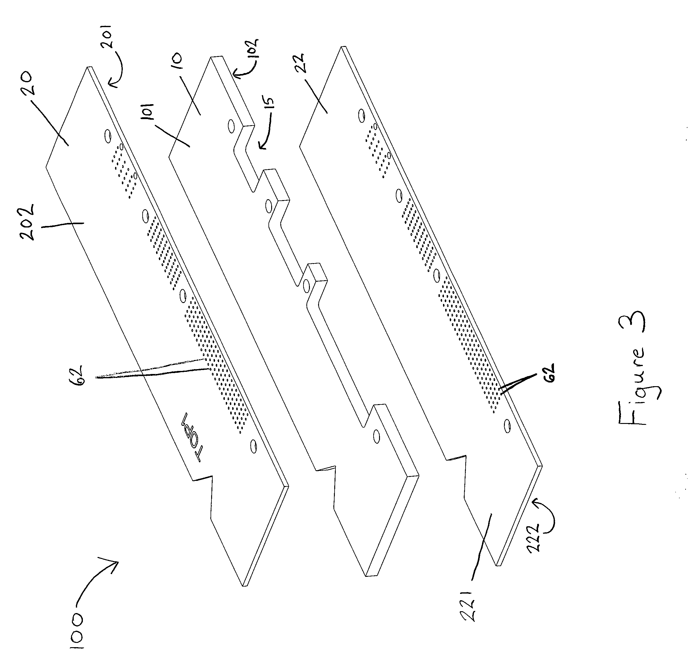
[0021]The heat sink member 10 may be any thermally conductive material, such as copper, gold, aluminum or composite, by way of example only. Referring to FIG. 3, the heat sink member 10 has a first surface 101 and an opposing second surface 102. The heat sink member 10 is typically of substantially uniform thickness and sub...
PUM
 Abstract
Description
Claims
Application Information