
Thin film photovoltaic module wiring for improved efficiency

a photovoltaic module and efficiency technology, applied in the direction of basic electric elements, electrical equipment, semiconductor devices, etc., can solve the problems of incompatibility with other system components, degradation over time, and suffer from tf pv modules, so as to reduce process complexity and reduce line width

Inactive Publication Date: 2008-01-31
APPLIED MATERIALS INC
View PDF12 Cites 41 Cited by
  • Summary
  • Abstract
  • Description
  • Claims
  • Application Information

AI Technical Summary

Benefits of technology

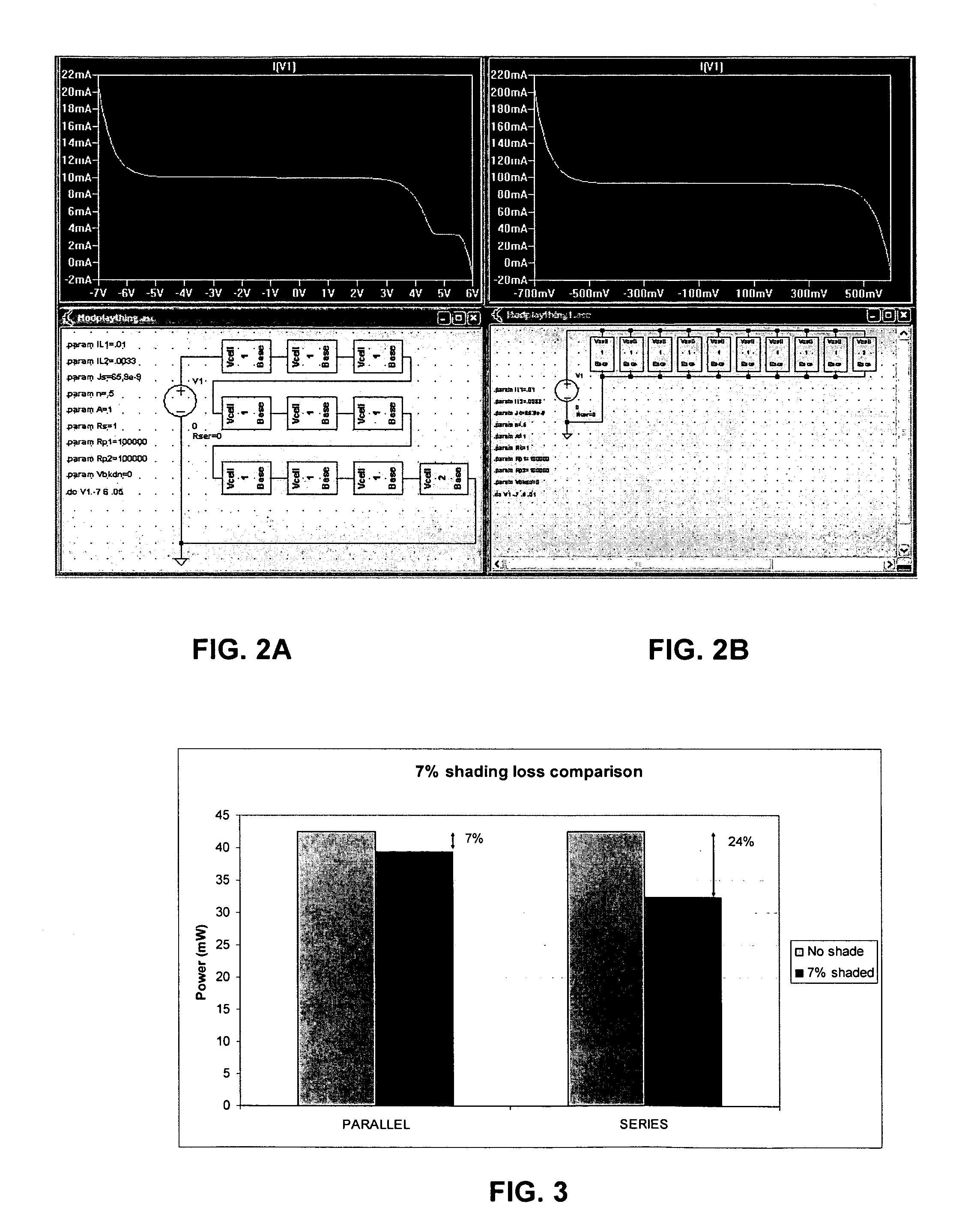
[0014]The present invention relates to configuring and wiring together cells in TF PV modules. According to one aspect, cells are fabricated on one plane on a top surface of a substrate, with wiring patterned on a parallel plane, and vias formed to provide connections between the cell plane and wiring plane. In one embodiment, the wiring plane is on the back surface of the substrate and vias are formed through the substrate. In another embodiment, the wiring plane is on the top surface of the substrate underneath the cell plane and an insulating layer, with the vias formed through the insulating layer. In another embodiment, the cell plane formed on the top surface includes superstrate cells that are illuminated through a transparent substrate, with an insulator between the cell plane and an upper wiring plane. According to another aspect, the heavy bus bar connections in the wiring plane can carry large currents and do not block light impinging on the cells. According to further aspects, the wiring plane enables use of parallel cell connections that provide immunity to shading, as described above. Moreover, these connections can be wired in a variety of methods, allowing use of series-parallel arrangements so that, for example, local regions could be parallel connected while larger regions series connected. According to still further aspects of the invention, once the substrate is prepared using plating and methods similar to those employed in printed circuit board manufacture, the fabrication process may require only two laser scribes, rather than the conventional three. This reduces line width, as fewer scribes must be registered to one another, as well as reducing process complexity. Unlike the prior art process, the scribes do not require selectivity, and can be done from the front. According to additional aspects of the invention, the back side wiring plane embodiment can also accommodate other components and structures such as protect diodes, switches and processors.

Problems solved by technology

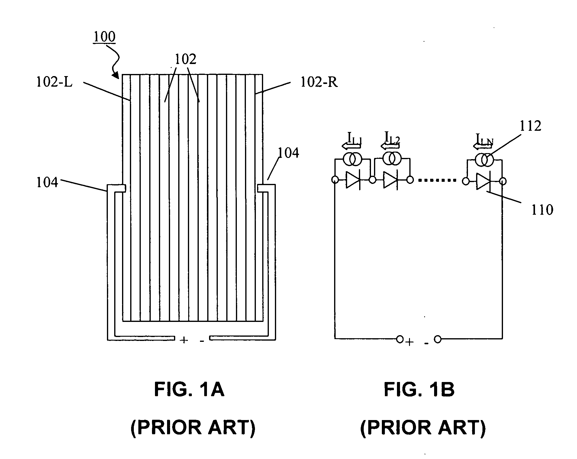
However, TF PV modules suffer from certain drawbacks such as incompatibility with other system components, degradation over time, losses due to shading and non-uniformities, and lower efficiency.
The series connection between cells, however, also introduces some limitations.
However, if one of the cells in the series string generates less current, it will limit the current that the module delivers.
For example, at the start and end of the day objects cast long shadows that may non-uniformly fall on a module.
Other factors include process variation (for example, non-uniformity in a deposition system) and degradation over time.
However it is caused, this current limitation can also damage the module.
Excess reverse bias can damage that cell.
However, it is difficult to install such diodes within thin film modules, as it is not easy to form terminals for such diodes using laser scribing.
Another problem hindering the adoption of conventional TF PV modules is that in practice, there are limitations on the size, shape and nature of the interconnect regions between cells.
Making narrower cells would also require more scribing time and increase cost.
Also, scribing is an ablative process, so it is easiest to make long, straight cuts and most difficult to make contact pads, regions exposing under-layers, or regions with complex, 2-dimensional shapes.
Although employing parallel connections provide benefits compared to completely series-connected modules, such benefits can prove fleeting.
For example, it may be difficult to provide parallel wiring between sub-modules on the same side of the glass substrate as the active regions.
Such wiring can block light, thereby reducing the potential benefits of the parallel wiring.
Moreover, the parallel wiring needs to accommodate potentially more current in a more confined area than occurs in across a fully series-connected module, which requires larger bus structures, which can also reduce or block the active areas.

Method used


Image

  • Thin film photovoltaic module wiring for improved efficiency
  • Thin film photovoltaic module wiring for improved efficiency
  • Thin film photovoltaic module wiring for improved efficiency

Examples


Embodiment Construction

[0027]The present invention will now be described in detail with reference to the drawings, which are provided as illustrative examples of the invention so as to enable those skilled in the art to practice the invention. Notably, the figures and examples below are not meant to limit the scope of the present invention to a single embodiment, but other embodiments are possible by way of interchange of some or all of the described or illustrated elements. Moreover, where certain elements of the present invention can be partially or fully implemented using known components, only those portions of such known components that are necessary for an understanding of the present invention will be described, and detailed descriptions of other portions of such known components will be omitted so as not to obscure the invention. In the present specification, an embodiment showing a singular component should not be considered limiting; rather, the invention is intended to encompass other embodimen...


PUM


Abstract

The present invention relates to configuring and wiring together cells in TF PV modules. According to one aspect, cells are fabricated on one plane on a top surface of a substrate, with wiring patterned on a parallel plane, and vias formed to provide connections between the cell plane and wiring plane. In one embodiment, the wiring plane is on the back surface of the substrate and vias are formed through the substrate. In another embodiment, the wiring plane is on the top surface of the substrate underneath the cell plane and an insulating layer, with the vias formed through the insulating layer. In another embodiment, the cell plane formed on the top surface includes superstrate cells that are illuminated through a transparent substrate, with an insulator between the cell plane and an upper wiring plane. According to another aspect, the heavy bus bar connections in the wiring plane can carry large currents and do not block light impinging on the cells. According to further aspects, the wiring plane enables use of parallel cell connections that provide immunity to shading, as described above. Moreover, these connections can be wired in a variety of methods, allowing use of series-parallel arrangements so that, for example, local regions could be parallel connected while larger regions series connected.

Description

FIELD OF THE INVENTION[0001]The present invention relates to methods for making interconnections used in thin film photovoltaic (TF PV) modules, and more particularly to improved interconnections that are provided on a plane parallel to a top surface where the cells are provided.BACKGROUND OF THE INVENTION[0002]TF PV modules offer many advantages over other types of photovoltaic modules such as modules based on silicon wafers, such as lower manufacturing cost and less consumption of materials with limited availability. However, TF PV modules suffer from certain drawbacks such as incompatibility with other system components, degradation over time, losses due to shading and non-uniformities, and lower efficiency. As a result, despite their inherent advantages, TF PV modules enjoy only about a 10% share of the market as compared to about a 90% share for silicon modules.[0003]To illustrate the conventional drawbacks even further, a conventional method for forming and configuring a TF PV...

Claims


Application Information

Patent Timeline
IPC IPC(8): H01L31/00
CPCH01L31/0465Y02E10/50H01L31/0445
Inventor BORDEN, PETER G.EAGLESHAM, DAVID J.
Owner APPLIED MATERIALS INC
Learn More