Support frame for use with lawn and refuse bags

a technology for supporting frames and refuse bags, which is applied in the direction of sports equipment, domestic objects, packaging goods, etc., to achieve the effects of high strength-to-weight ratio, increased bag engagement area, and strong durability

Inactive Publication Date: 2008-01-31
ARMALY JOHN W JR
View PDF23 Cites 24 Cited by
  • Summary
  • Abstract
  • Description
  • Claims
  • Application Information

AI Technical Summary

Benefits of technology

[0017] Importantly, the shaped opening openings not only enhance gripping connection with the bag material but also enhance inward / outward flexure of the beam relative to the sidewall from which cantilevered.
[0019] Preferably, the U-shaped slit is symmetrically centered on a perpendicular that extends between the top and bottom edges of the sidewall and the slit defines first, second and third edges, the first and second edges being symmetrically disposed and at an acute angle to the perpendicular and the third edge generally parallel to the top edge of the sidewall and joining the first and second edges, the transition between the third edge with each of the first and second edges being rounded to increase bag engagement area and to obviate cutting the bag material.
[0020] Further, the one-piece retention frame is preferably formed of a material that is lightweight, moisture resistant, and notable for stiffness and durability and high strength to weight ratio. A preferred material is cardboard and like paper products made of unbleached kraft paper, with two heavy outer layers and a wavy inner layer to provide strength, and possibly comprised of recycled fibers and coated to form a moisture barrier when collecting wet leaves, thereby enabling use and reuse of the retention frame.
[0021] According to an important aspect of this embodiment, the wavy inner layer comprises a succession of parallel ridges and grooves, which are oriented parallel to the top and bottom edges of the frame, the inner layer operating to reduce the ability of the side wall to resist a bending force resulting from the flange deflecting outwardly to fit about the upper end portion of the bag.
[0025] Additionally, the sidewall is punched to form a keyhole-shaped opening at each end of the outer slit, and form a pivot line or axis, in a manner described hereinabove. Importantly, the keyhole shaped openings enhance gripping connection with the bag material but also enhance inward / outward foldability of the U-shaped handle or outer beam relative to the sidewall from which cantilevered.

Problems solved by technology

In the prior art, there are many bag holders, but these prior art bag holders have numerous deficiencies.
For example, some of the known bag holders may be inconvenient to erect, may collapse at inopportune times, and may be unstable when the bag is filled.

Method used


Image

  • Support frame for use with lawn and refuse bags
  • Support frame for use with lawn and refuse bags
  • Support frame for use with lawn and refuse bags

Examples


Embodiment Construction

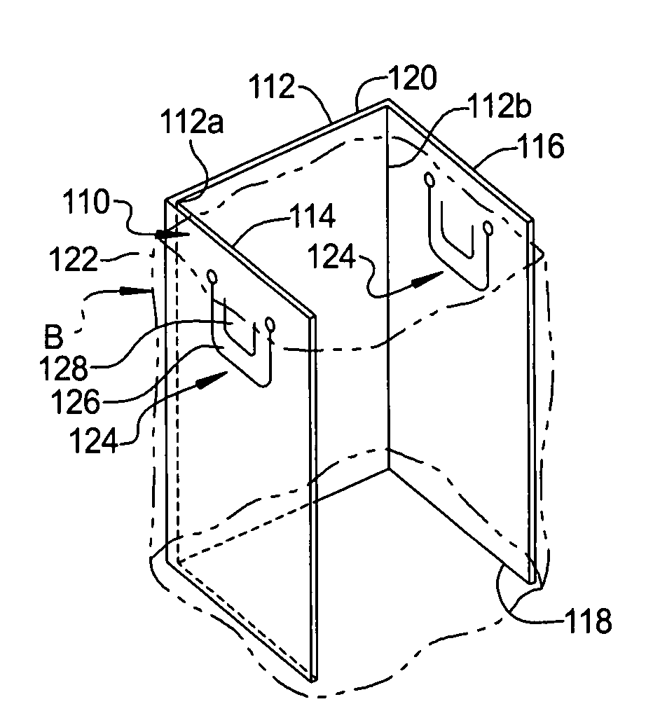
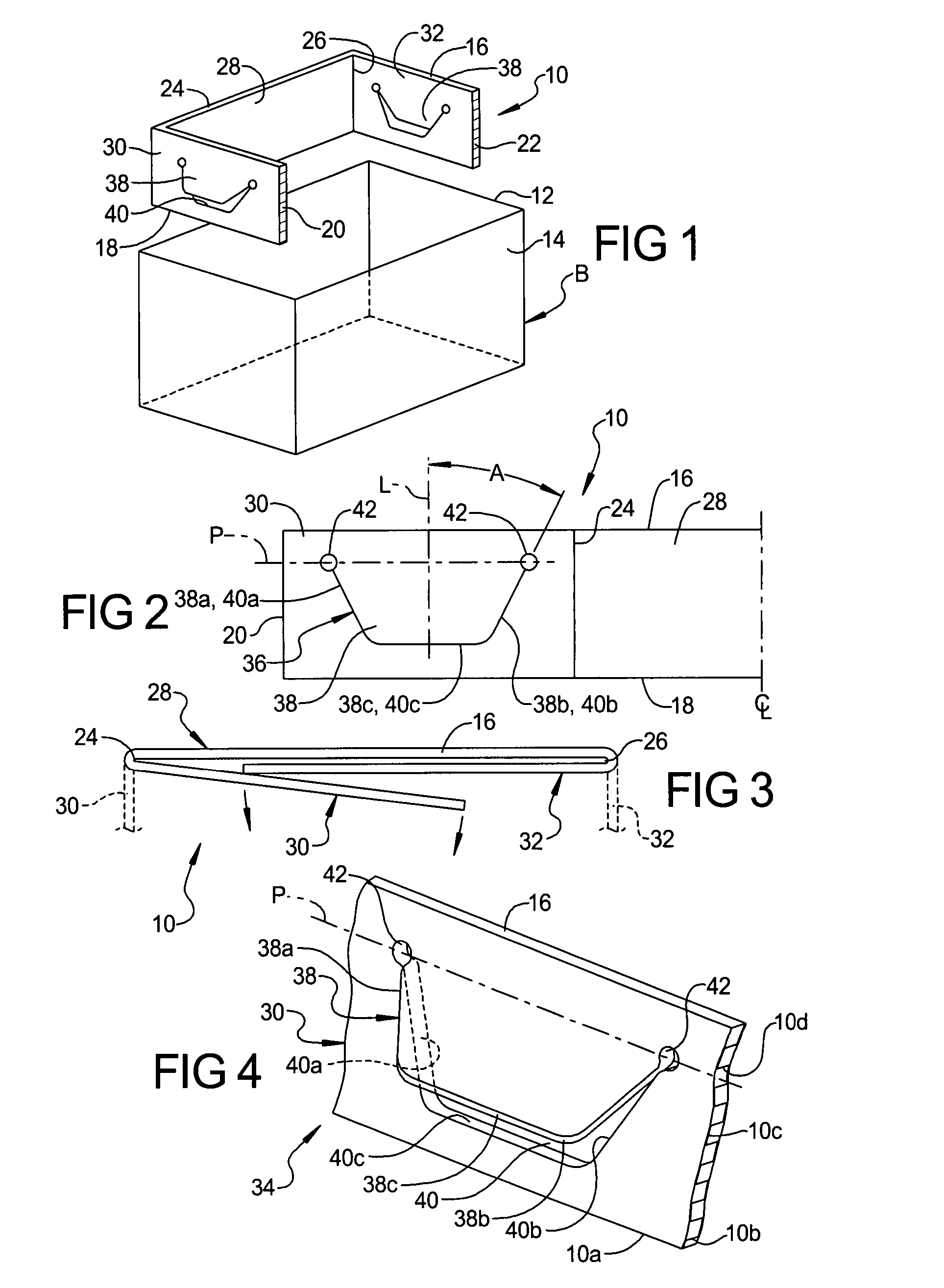
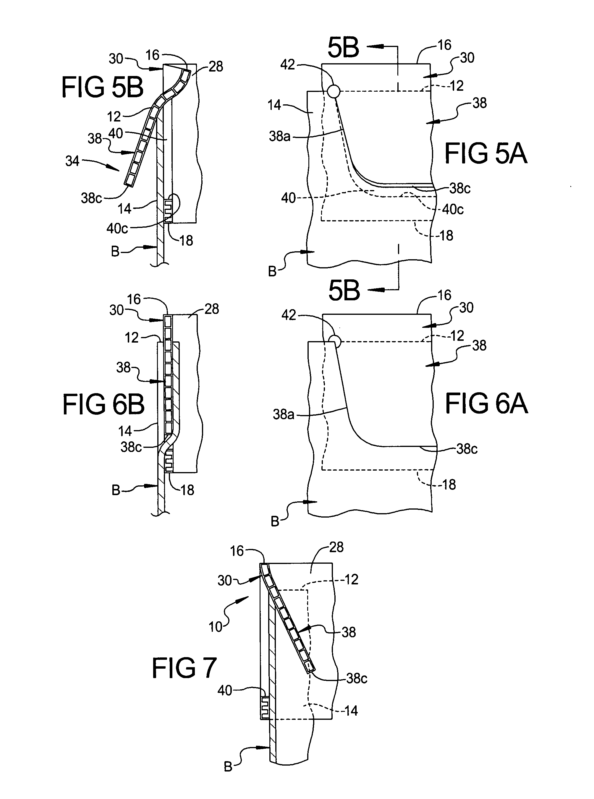
[0045] Referring now to the drawings, there is illustrated embodiments of a bag support or retention frame according to this invention. In a first arrangement, a support frame is fittable atop a self-standing generally rectangularly open paper lawn bag. In another arrangement, a support frame is adapted to be fittable within in a paper or non-self standing plastic bag and extend from the top to the bottom thereof

[0046] According to the first arrangement, FIG. 1 illustrates a bag support or retention frame according to this present invention, generally indicated by the reference number 10 positioned atop a top end 12 of and insertion, at least in part, into the upper end portion 14 of a lawn and refuse bag or the like, generally indicated at “B”. The upper end portion 14 of the bag “B” is openable and typically forms a rectangular shaped entryway into the interior of the bag.

[0047] Generally, the bag “B” is conventionally available in the marketplace and is comprised of a material ...


PUM


Abstract

A C-shaped support frame fits to the upper entry of a lawn and / or refuse bag to hold the bag open for receiving leaves or waste. The support frame includes retention structure in the form of a pair of deflectable beams and associated cutouts, each of U-shape, wherein the bag material is engaged by the beam when the beam is snap-fitted back into the cutout associated therewith. The retention structure may include two pairs of U-shaped beams, the beams of each pair being relatively deflectable and grippingly engageable with the bag material when the beams are snap-fitted into their respective cutouts.

Description

CROSS-REFERENCE TO RELATED APPLICATIONS [0001] This application claims the benefit of U.S. Provisional Application No. 60 / 830,031, and U.S. Provisional Application No. 60 / 849,666, filed Oct. 5, 2006, each titled “Support Frame for Use With Leaf Bags”, filed Oct. 5, 2006, and the entire disclosure of each incorporated herein by reference for all purposes.BACKGROUND OF THE INVENTION [0002] 1. Field of the Invention [0003] This invention relates, in general, to a support frame for use with lawn and refuse bags or the like; and in particular, to an improved support frame for removable attachment to the top entry of such bag for rigidifying and maintaining the bag upwardly open to receive materials deposited therein. [0004] 2. Discussion of Related Art [0005] In the prior art, there are many bag holders, but these prior art bag holders have numerous deficiencies. For example, some of the known bag holders may be inconvenient to erect, may collapse at inopportune times, and may be unstabl...

Claims


Application Information

Patent Timeline
Patent Type & Authority Applications(United States)
IPC IPC(8): B65B1/04
CPCB65B67/12B65F2240/138B65F1/1415
Inventor ARMALY, JOHN W. JR.
Owner ARMALY JOHN W JR
Why Eureka
Try Eureka