DC-DC converter

a converter and converter technology, applied in the field of dc-dc converters, can solve the problems of increasing current consumption in the control circuit, complicated circuit configuration, and reducing power conversion efficiency, and achieve the effect of reducing current consumption and reducing current consumption

Active Publication Date: 2008-01-31
FUJI ELECTRIC CO LTD
View PDF13 Cites 35 Cited by
  • Summary
  • Abstract
  • Description
  • Claims
  • Application Information

AI Technical Summary

Benefits of technology

[0010]In such a DC-DC converter, because the ON time of the switching element is linked to at least one of the input voltage change and the output voltage change by the control circuit performing PFM control, reduction of current consumption can be obtained by means of a simple configuration and the switching frequency decreases in the light load case regardless of a change of the input voltage and the output voltage, and further, it is possible to operate at an approximately constant switching frequency in the heavy load case.
[0011]It is advantageous that in the

Problems solved by technology

However, in the case where the input voltage varies due to the drain of a battery or use of a plurality of power supplies, or in the case of use after the output voltage is set arbitrarily, because the switching frequency is varied by an operating condition, power conversion efficiency is reduced.
However, in the conventional DC-DC converter as described above, in the case where the switching

Method used


Image

  • DC-DC converter
  • DC-DC converter
  • DC-DC converter

Examples


Embodiment Construction

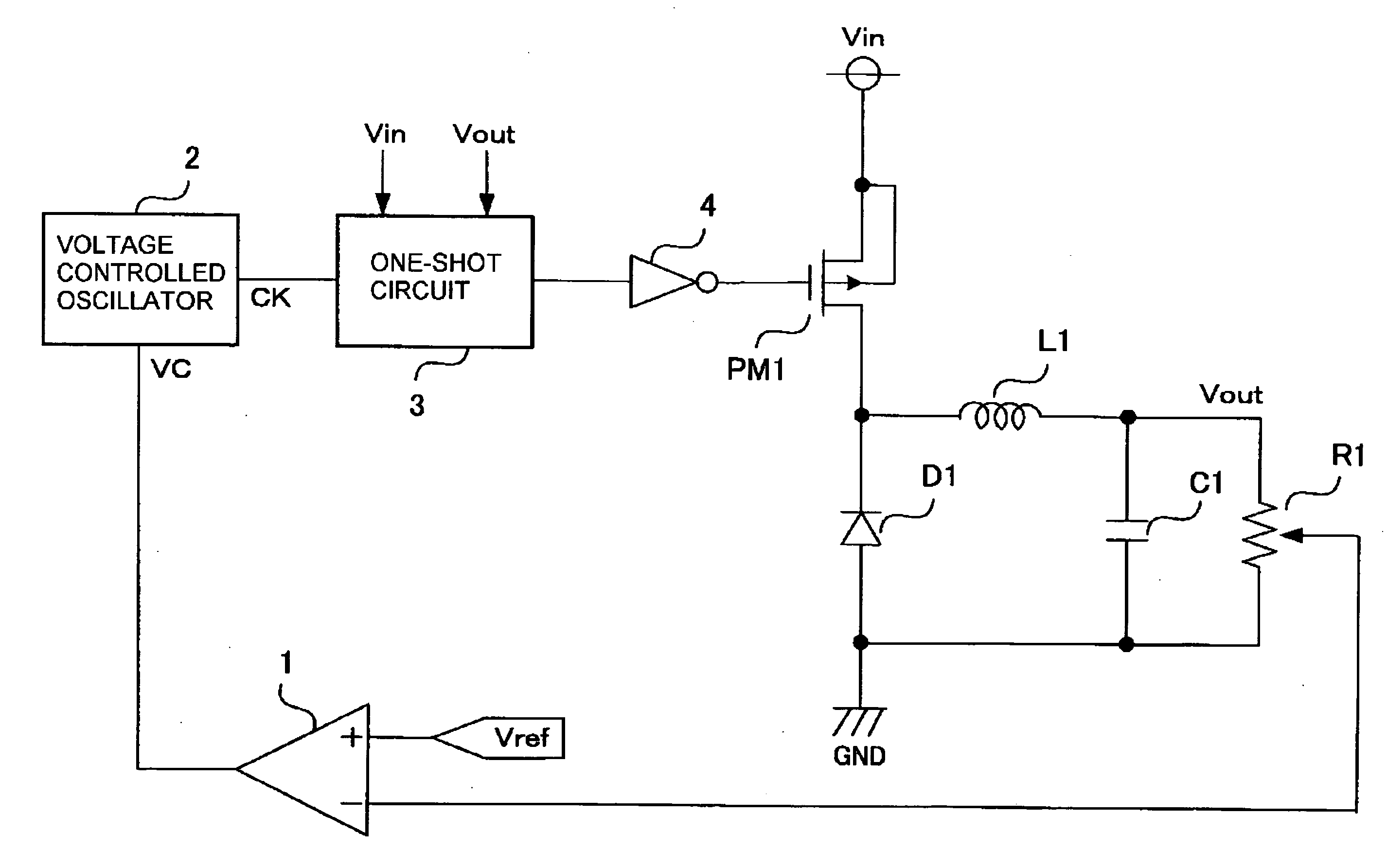
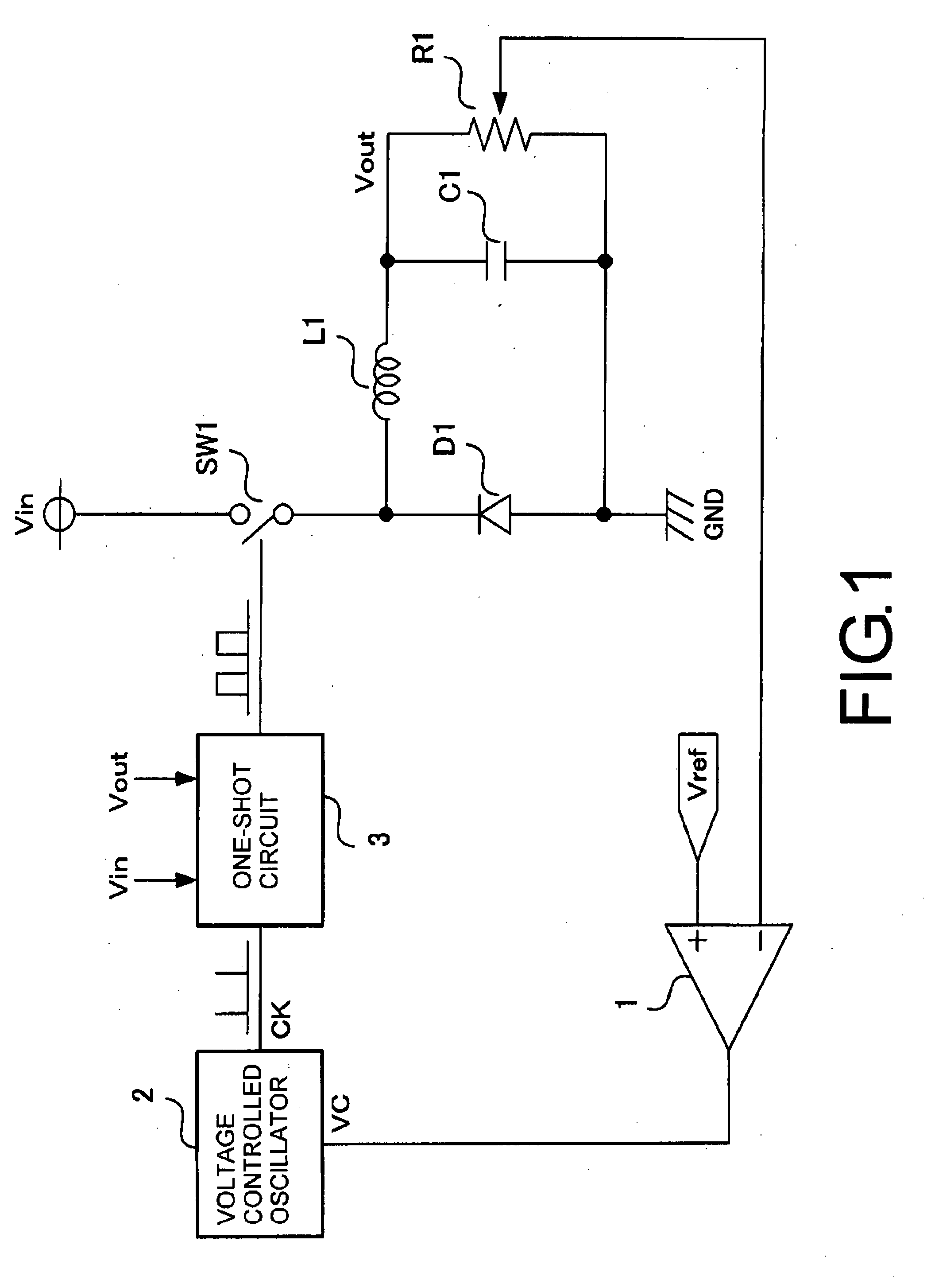
[0019]A preferred embodiment of a DC-DC converter according to the invention is explained in detail with reference to the attached drawings. FIG. 1 is a view showing the basic configuration of a DC-DC converter according to a preferred embodiment of the present invention. The DC-DC converter is a step-down converter that controls direct current power based on switching an input direct current on and off by means of an electric switch SW1, and includes a control circuit performing PFM control in which an ON time of the electric switch SW1 is fixed and an OFF time is variable. The ON time of the electric switch SW1 is linked to at least one of the input voltage change and the output voltage change by the control circuit performing PFM control. Concretely, the ON time of the electric switch SW1 decreases with rise of the input voltage Vin or increases with rise of the output voltage Vout.

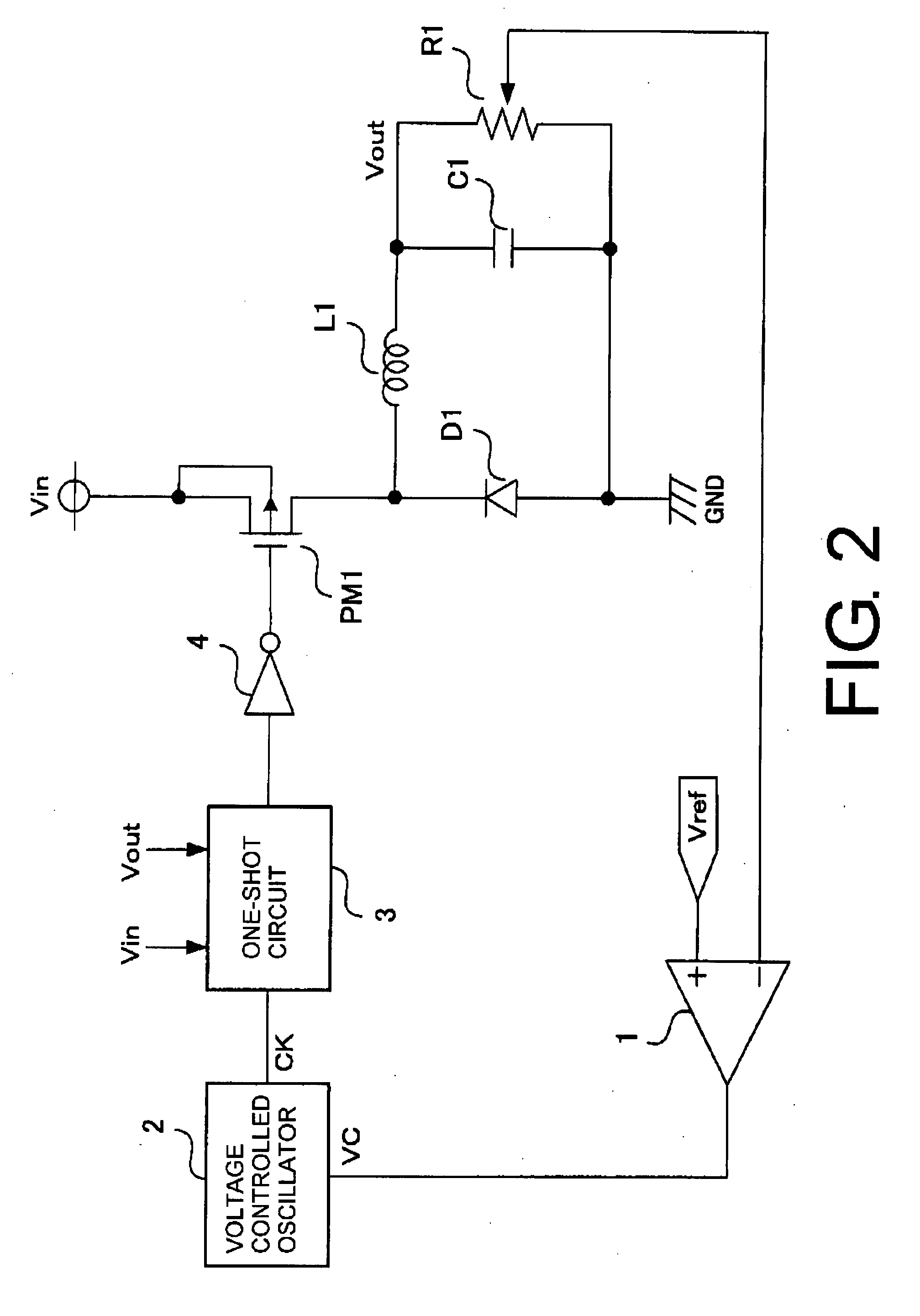
[0020]The control circuit includes an error amplifier 1 including an operational amplifier amplifyi...


PUM


Abstract

A DC-DC converter performing pulse frequency modulation (PFM) control with a fixed ON time, having a control circuit performing PFM control of the ON time for a switch, including an error amplifier amplifying the difference between an output voltage and a target voltage, a voltage controlled oscillator increasing and decreasing in frequency and outputting an error signal, and a one-shot circuit generating the ON time based on a trigger signal output from the VCO, where ON time is linked to an input voltage and/or an output voltage. The switching frequency decreases under light loads and current consumption is reduced, and the switching frequency is made to be approximately constant under heavy loads.

Description

BACKGROUND OF THE INVENTION[0001]1. Field of the Invention[0002]The present invention relates to a DC-DC converter performing DC-DC (direct current-direct current) conversion by switching a switching element ON and OFF, and in particular to a DC-DC converter employing Pulse Frequency Modulation (hereinafter referred as PFM) control of a fixed ON time of the switching element.[0003]2. Related Art[0004]In recent years, in DC-DC converters used as a power supplies of portable devices and the like, reducing current consumption in a standby mode has been requested. PFM control of a fixed ON time is a control technique which adjusts an output voltage of the DC-DC converter by fixing an ON time of the switching element of the DC-DC converter and varying an OFF time of the switching element, and when there is little load current, the DC-DC converter operates in a discontinuous current mode and a switching frequency decreases in approximate proportion to decreasing of a load current. Therefo...

Claims


Application Information

Patent Timeline
IPC IPC(8): G05F1/44
CPCH02M3/156H02M1/08
Inventor YAMADA, KOUHEI
Owner FUJI ELECTRIC CO LTD
Why Eureka
Try Eureka