This helps you quickly interpret patents by identifying the three key elements:
Problems solved by technology
Method used
Benefits of technology
Benefits of technology
[0009]The present invention provides a key system that eliminates the need for carrying a plurality of keys including a key that imposes conditional use when entrusting a third party with the key to drive the vehicle.
Problems solved by technology
If the vehicle owner does not have either one of the key and the communicable data medium on hand, the first authentication or the second authentication is unsuccessful.
Method used
Image
Click on the blue label to locate the original text in one second.
Reading with bidirectional positioning of images and text.
Examples
first embodiment
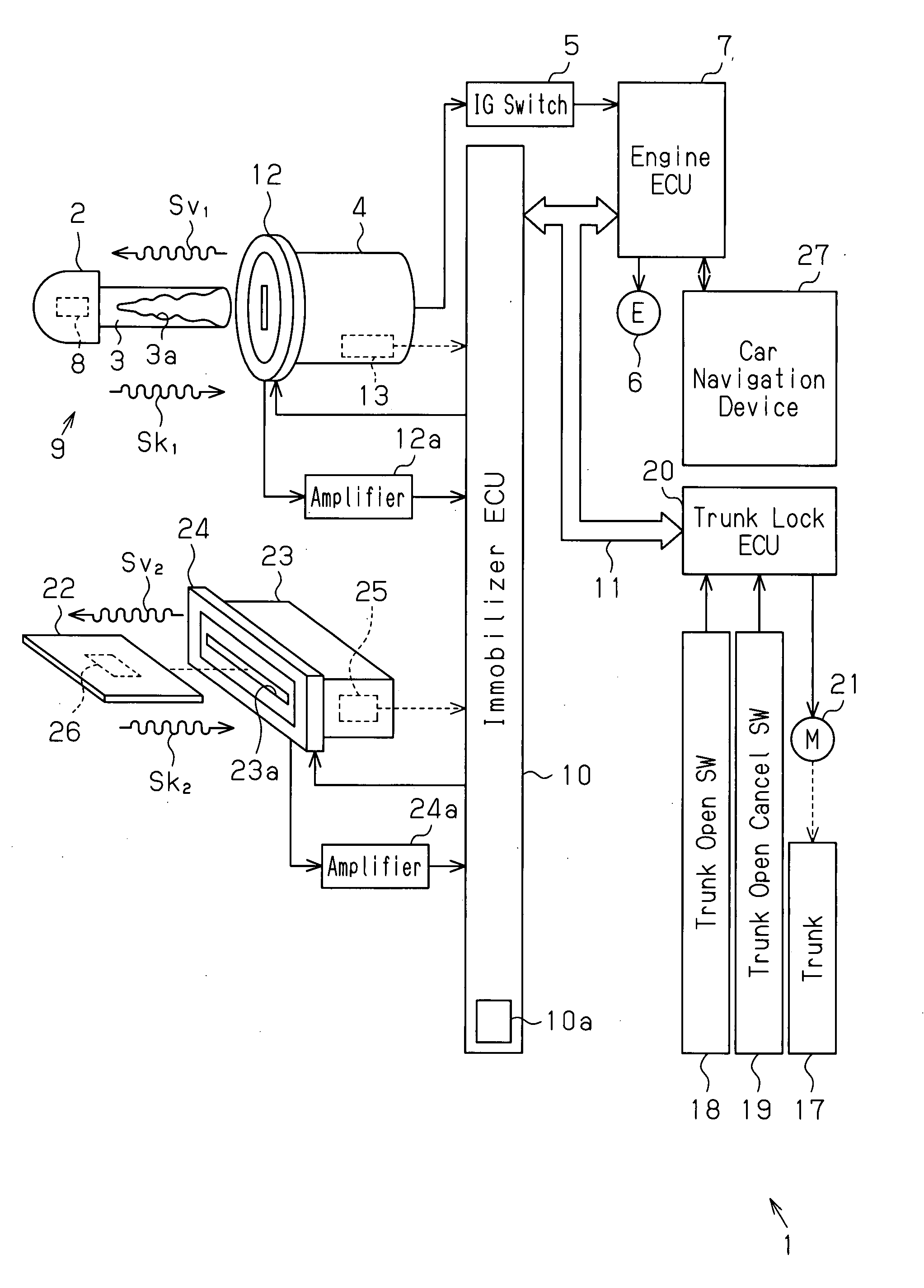
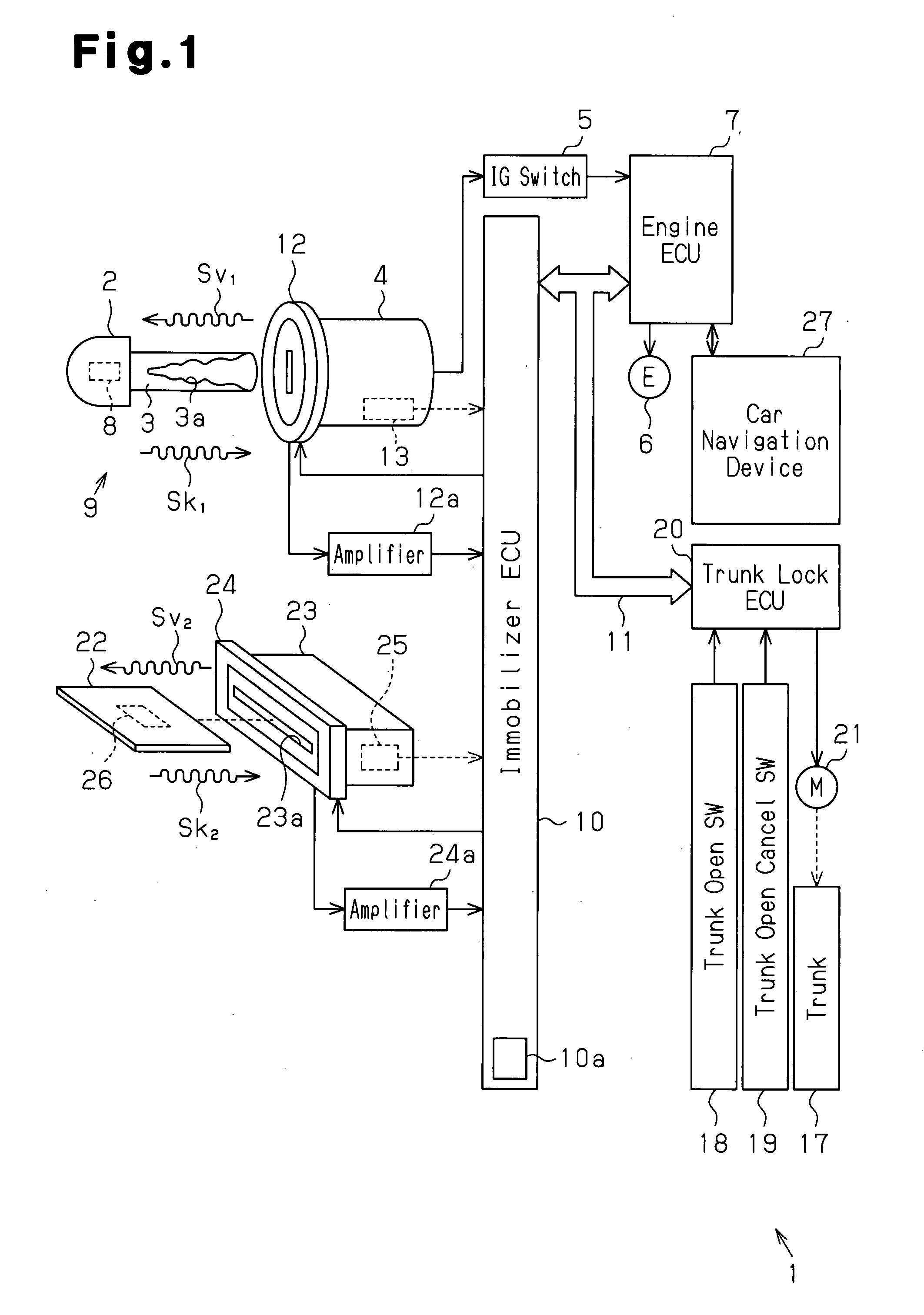
[0040]A key system according to the present invention will now be described in detail with reference to FIGS. 1 to 5.
[0041]As shown in FIG. 1, a vehicle 1 has a key cylinder 4 located near a steering wheel in the passenger compartment. A mechanical key 2, which corresponds to a typical master key, is used to perform various operations in the vehicle 1 (lock and unlock doors, start an engine, lock and unlock a glove compartment, and open a trunk lid). The vehicle 1 is one example of an operation subject of the present invention. The mechanical key 2 is one example of a key of the present invention.
[0042]The key cylinder 4 is connected to an ignition (IG) switch 5 that is electrically connected to accessories (not shown) and an engine ECU (electronic control unit) 7. If the mechanical key 2 is an authorized key, that is, if the mechanical key 2 has a key plate 3 including a proper key groove 3a (key code) 3a, the key cylinder 4 permits the mechanical key 2, when inserted in the key cy...
second embodiment
[0101]The operation of the key system of the second embodiment will now be described.
[0102]To drive the vehicle 1, the vehicle owner first inserts the ID card 22 into a card receptacle 23 arranged in a glove compartment 14. When a cylinder lock 15 of the glove compartment 14 is locked, the cylinder lock 15 cannot be unlocked by wireless communication with the portable remote controller 28. Thus, the vehicle owner removes the emergency key 48 from the portable remote controller 28 and uses the emergency key 48 to unlock the cylinder lock 15 and open the glove compartment 14. The vehicle owner then inserts the ID card 22 into the card receptacle 23.
[0103]The immobilizer ECU 10 detects that the ID card 22 has been inserted in the card receptacle 23 with a card switch 25. The immobilizer ECU 10 then intermittently transmits a second drive radio wave Sv2 from a second coil antenna 24 to perform the ID card authentication with the second transponder 26, which is embedded in the ID card 22...
third embodiment
[0128]In the third embodiment, the glove compartment 14 is locked and unlocked through wireless communication. This eliminates the need for performing an actual mechanical key operation to lock and unlock the glove compartment 14. Thus, the glove compartment 14 is easily locked and unlocked. Further, the vehicle 1 may be driven with only the ID card 22 and without the portable remote controller 28 on hand. In such a state, conditions are imposed on the driving of the vehicle 1. However, since the vehicle 1 can be driven with just the ID card 22, this structure may be used for various applications.
[0129]The third embodiment has the advantages described below in addition to the advantages of the first and second embodiments.
[0130](13) The electric lock 49 is used as the lock of the glove compartment 14. The glove compartment 14 is locked and unlocked through wireless communication performed with the portable remote controller 28. Thus, the glove compartment 14 is locked and unlocked w...
PUM
Abstract
A key system includes a first authentication part configured to perform first authentication for determining whether or not a unique key code of a key is registered in the operation subject and to permit an operation subject to operate in a state in which a first group of functions is operative when the first authentication generates an affirmative result. A wirelesssignalreceiver is configured to receive a medium code unique to a portable communicable data medium through wireless communication. A second authentication part is configured to perform second authentication for determining whether or not the medium code received by the wirelesssignalreceiver is registered in the operation subject. A condition-imposing part is configured to limit operative functions of the operation subject to a second group of functions that is more limited than the first group of functions when at least either one of the first authentication and the second authentication generates a negative result.
Description
CROSS-REFERENCE TO RELATED APPLICATIONS[0001]This application is based upon and claims the benefit of priority from prior Japanese Patent Application No. 2006-206646, filed on Jul. 28, 2006, the entire contents of which are incorporated herein by reference.BACKGROUND OF THE INVENTION[0002]The present invention relates to a key system for activating a lock device by, for example, performing a mechanical operation with a mechanical key or a wireless communication operation with an electronic key.[0003]Conventional keys for a vehicle include a master mechanical key and a sub-mechanical key (for example, refer to Japanese Laid-Open Patent Publication No. 6-167148). The master mechanical key is mainly used by the vehicle owner. The sub-mechanical key is used when the master mechanical key is not on hand. The conventional master mechanical key may be used to lock and unlock any lock in the vehicle, whereas the use of the sub-mechanical key is conditional. Thus, the sub-mechanical key cann...
Claims
Application Information
Patent Timeline
Application Date:The date an application was filed.
Publication Date:The date a patent or application was officially published.
First Publication Date:The earliest publication date of a patent with the same application number.
Issue Date:Publication date of the patent grant document.
PCT Entry Date:The Entry date of PCT National Phase.
Estimated Expiry Date:The statutory expiry date of a patent right according to the Patent Law, and it is the longest term of protection that the patent right can achieve without the termination of the patent right due to other reasons(Term extension factor has been taken into account ).
Invalid Date:Actual expiry date is based on effective date or publication date of legal transaction data of invalid patent.

